NodeMCU ESP8266 Evaluation & Review Project
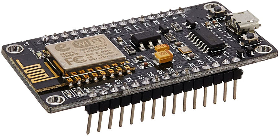
The NodeMCU ESP8266 is a cheap (less than £4) ESP8266 based processor with on-board Wi-Fi. NodeMCU is not really Arduino but, it is close enough that the Arduino IDE and my own Arduino library of code can be used on it.
Like all Arduino devices, it is really quite powerful and can be programmed to work with many types of sensors and devices, connecting them to my contextual smart home. One Arduino processor can also be used to do several things or connect many sensors/devices.
The objective of this project is purely to assess the reliability of this Wi-Fi connected processor when powered by batteries, to see if it can be used to connect distant sensors to my contextual smart home. I also plan to investigate options for solar recharging of the batteries, to avoid the need to have to recharge them manually or replace them.
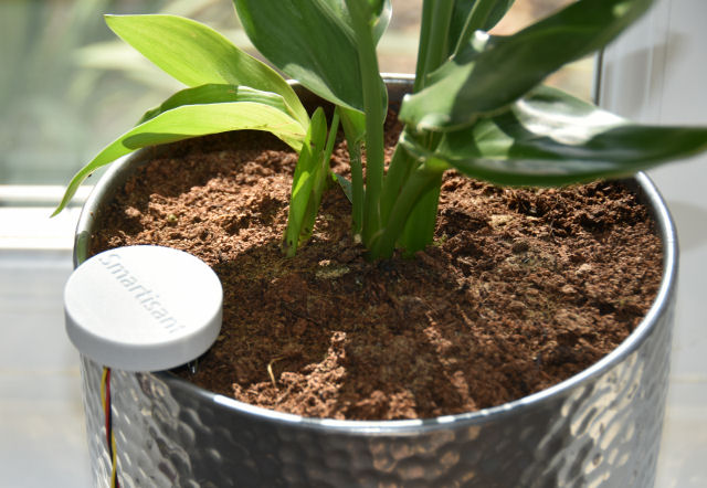
My first test case is going to be my Smartisant Soil Moisture Sensor SML1. This is a wired sensor that is ideally suited to working with the 5V supply and analogue input ports on devices like the Arduino Uno or Arduino Mega 2560 but, it can also work with the 3.3V exposed by the NodeMCU ESP8266.
Specifications
The NodeMCU ESP8266 features a Tensilica 32-bit RISC CPU Xtensa LX106 (80MHz clock speed) which operates at 3.3V. It has 4MB of Flash memory and 64K of SRAM. An on-board voltage regulator allows input voltages from 7-12V. It has 16 digital IO pins, 1 analogue input. It also supports SPI and I2C.
It also features on-board 2.4GHz Wi-Fi and has a PCB antenna giving good range. A micro-USB port enables it to be powered and programmed.
Power Options
I'm still investigating the best options to power the NodeMCU ESP8266 but, this is an interesting article on the best battery to use, which suggests that a LiFePO4 battery is the best option. For now, I've gone with 18650 3.7V Li-ion batteries though.
Power Management
One of the things I'm doing is measuring how long the processor is awake for. I need to minimise this as much as possible, in order to reduce overall power consumption. There is a fairly large variation due to the time it takes to connect to Wi-Fi. The kind of times I've seen the processor awake for so far are: 2988ms, 4866ms, 6856ms, etc. Basically, it can take from about 1 second to 8 seconds to connect to Wi-Fi and capture and send sensor data.
My Smartisant Soil Moisture Sensor SML1 sensor uses just a few mA but, with the processor in deep sleep this would be the most significant load on the battery. Because the sensor uses so little power though, I can connect the sensor supply wire directly to an output pin on the processor and only enable it when the processor is awake and needs to take a measurement.
Wi-Fi Connection
One of the things I'm currently looking at is whether it takes longer to connect to Wi-Fi using DHCP than a fixed IP address. All my research to date suggests that it does. I'm now testing with a fixed IP address.
Power Monitoring
I avoid batteries in my smart home as much as possible. Where I do have to use them, I always monitor battery level. This enables my Home Control System to keep track of them and send me a notification when a battery needs replacing or recharging.
The challenge with this processor it that it only has one analogue input port and I plan to use this with my Smartisant Soil Moisture Sensor SML1. My plan is to use the CD4051BE digitally controlled analogue switch IC, to enable several up to 8 analogue devices to be used with the one analogue port available.
Because this processor is a slave processor in my smart home architecture and sends a 'regular' heartbeat, my Home Control System will know when the battery is flat as the slave will go 'missing'. A simple bit of configuration will then result in me getting a notification.
Whilst the processor can handle 3.65V maximum, the analogue input pin can't. This means a voltage divider is required and I have to be careful to make sure this doesn't become a significant load on the battery. This means using a high impedance voltage divider. I'm using a 47KΩ resistor on the high side, in series with a 100KΩ potentiometer to ground. This means the voltage seen by the analogue input pin is about two-thirds of the battery voltage (at the mid-point) and the potentiometer gives me the ability to calibrate this too. This 147KΩ load draws just 25µA from the battery.
Data Retention
One thing I need to do is to retain data though the deep sleep, so that the processor can keep track of things longer term. One of these things is the 'heartbeat' counter.
There are basically 4 types of memory available on the ESP8266:
- RAM data will be lost after a power cycle or deep sleep. Unlimited write cycles. Amount of storage depends of how much RAM is used by other data.
- RTC memory data will be lost after power cycle but will persist through deep sleep. 768 bytes of storage. Unlimited write cycles.
- EEPROM is actually the flash memory being used to emulate EEPROM. Data will persist through power cycle and deep sleep. 4096 bytes of storage.
- SPIFFS data will persist through power cycle and deep sleep.
For my use case, the RTC memory looks like the best bet and this is well described here.
Using the RTC memory worked well and I have managed to get persistent values stored through deep sleeps. The real challenge was in initialising the RTC memory on restart. There is no mechanism to do this and the solution is to use the memory to also store an associated checksum for each value stored. If the checksum isn't correct then you can assume the memory needs to be initialised. This approach works perfectly! :-)
Analogue Input(s)
There is only one analogue input pin and the ADC has a 10-bit resolution, which means you will get values between 0 and 1023. The ESP8266 ADC pin input voltage range is 0 to 1V if you are using the bare chip. The NodeMCU ESP8266 board comes with an internal voltage divider, so the input range is 0 to 3.3V. I tested this with a potentiometer and a multimeter before I connected any sensors.
Phase 1 Build
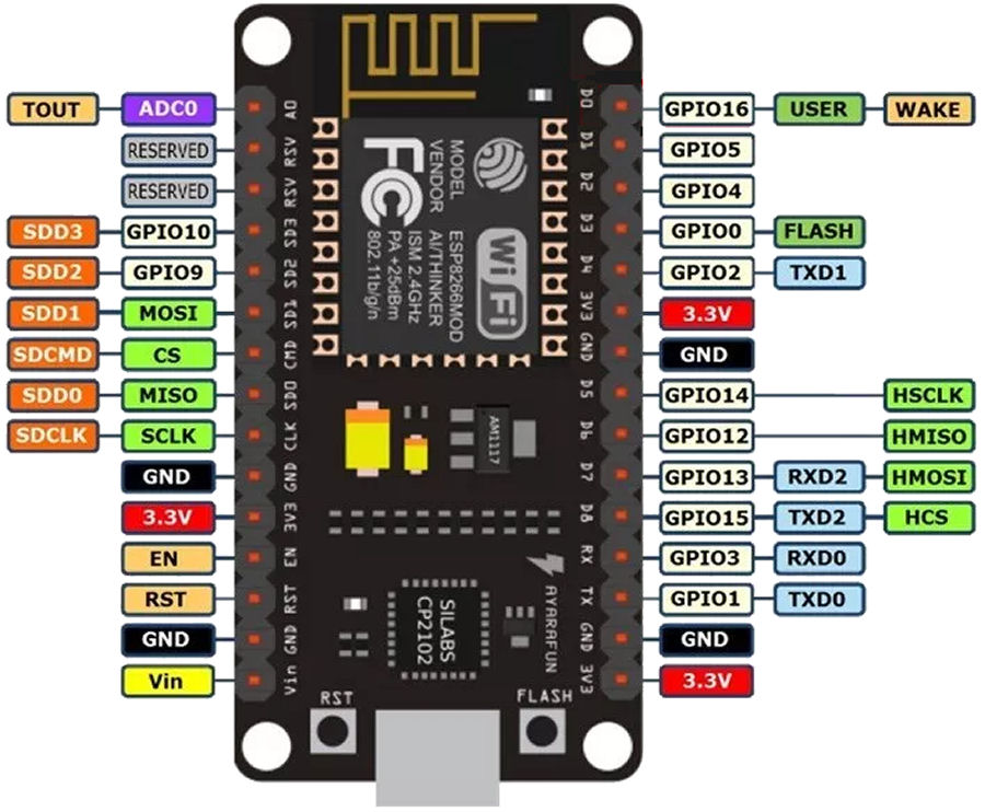
To use timer wake up with ESP8266, you need to connect the RST pin to GPIO 16 which is labelled as D0, in a NodeMCU board. If you take a look at the NodeMCU pinout, you can see that GPIO 16 is a special pin and it has a WAKE feature.
The RST pin of the ESP8266 is HIGH while the ESP8266 is running. When the RST pin receives a LOW signal, it restarts the microcontroller. If you set a deep sleep timer with the ESP8266, once the timer ends, GPIO 16 goes LOW pulling the RST pin LOW, to wake up the ESP8266 after a set period of time.
digitalWrite(5, HIGH).
Before you can program the board using the Arduino IDE, you need to install support for the board using the 'Boards Manager' and then by going to 'Tools' and selecting 'NodeMCU (ESP-12E Module)'.
Deep Sleep Duration
The function ESP.deepSleep(microseconds, mode) will put the processor into deep sleep. The mode is optional and can be one of:
- WAKE_RF_DEFAULT
- WAKE_RFCAL
- WAKE_NO_RFCAL
- WAKE_RF_DISABLED
The processor can sleep for at most ESP.deepSleepMax() microseconds.
ESP.deepSleepMax() is dependent on ambient temperature. A lower temp means a shorter sleep duration and a higher temp equates to a longer sleep duration.
If you implement deep sleep with WAKE_RF_DISABLED and require WiFi functionality on wake up, you will need to implement an additional WAKE_RF_DEFAULT before WiFi functionality is available.
In earlier versions of the SDK, the maximum value for a 32-bit unsigned integer (a uint32_t) is 4294967295 or 0xffffffff, hence the maximum deep sleep interval was about 71 minutes. With SDK 2.1 Espressif changed the data type of that parameter to a 64-bit unsigned integer (a uint64_t), so in theory you could send the processor into a deep sleep for about 5,124,095,576 hours. In practice this doesn't work though and the maximum limit is much less and given its own value of ESP.deepSleepMax().
When I used the code:Serial.println("max deep sleep = " + uint64ToString(ESP.deepSleepMax()))this gave me a value of 13539213305µs = 13539 seconds = 225.6 minutes = 3.76 hours = 3 hours and 45 minutes. This is obviously less than expected but still much more than the 71 minutes from earlier versions of the SDK.
Multiple Analogue Inputs
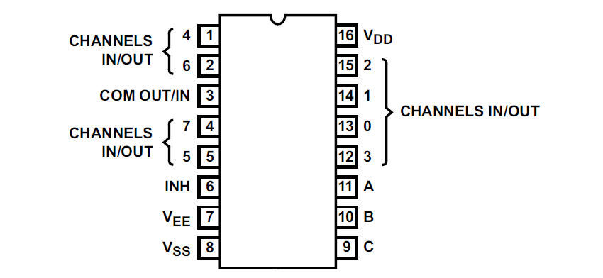
My plan is to use the CD4051BE IC, to see if I can use it to enable an 8-channel digitally controlled analogue switch and thus read up to 8 different analogue sensors, via the one analogue input pin.
This device uses 3 pins to select one of 8 analogue inputs but I don't need to use all of them for this application. The 3 pins C, B, A are used to select the input channel, with C being the most significant bit. So with all all three LOW, input 0 is selected. With all three HIGH, input 7 is selected.
The IC also features an 'inhibit' pin (INH / pin 6), which can be used to disconnect all inputs. I've chosen to map the NodeMCU ESP8266 pins to the following CD4051BE pins:
- INH [6] = GPIO15 / D8
- C [9] = GPIO14 / D5
- B [10] = GPIO12 / D6
- A [11] = GPIO13 / D7
The input channels currently in use are:
- CH0 = Battery voltage
- CH1 = Soil moisture sensor
Smart Home Integration
Over my many years doing smart home (I started in 2004), I have developed my own library of code for Arduino processors and this includes functions to integrate it into my distributed Home Control System and connect numerous types of sensors. These 'slave processors' can then do clever stuff like local control, self-monitoring of performance, local signal conditioning and rate limiting, send warnings and errors, or host some functions locally.
This maximises reuse across my many smart home projects, making it very quick and easy to develop and test new smart home capabilities. My smart home also employs the concepts of technology abstraction, meaning my smart home is also technology agnostic. This allows old technologies or broken sensors and devices to be swapped out with new ones, with minimal effort and zero reconfiguration.
Most of the Arduino processors installed in my smart home use an Ethernet IP network interface, to enable them to send and receive events with my Home Control System, using my unified communications protocol. Wired networks ensure very low latency and hence a great user experience, though occasionally I will use Wi-Fi.
Adding sensors and devices to my Home Control System is simply a matter of adding one line of JSON for each one, to the main configuration file. This defines the name, zone, object type and also the details of the slave processor it is hosted or controlled by. All the intelligence is within my Home Control System, which receives and sends encrypted events using my unified communications protocol. It sends events to update my smart home on things like the temperature, humidity, fan state, appliance and lighting state changes, occupancy, etc.
This processor uses Wi-Fi to enable it to send events to my Home Control System, using my unified communications protocol. I typically use a wired network as it is the only way to get very low latency and hence a great user experience but, sometimes it just isn't possible. The whole point about this project was to test how well Wi-Fi enabled, battery powered devices work.
Phase 1 Testing
Using my own library of code, it was very quick and easy to get the processor to do the following:
- Wake up and start awake timer.
- Enable sensor power, currently just a blue LED with a 1KΩ resistor for now.
- Connect to Wi-Fi.
- Send a heartbeat event.
- Send a test event to my Home Control System, requesting that it sends me a notification.
- Disable sensor power.
- Enter deep sleep mode for a long time duration.
When I tried the ESP.deepSleepMax(), the processor would not wake up as expected, so I started with the sleep time set to one hour. The wake up times were: 15:58:31, 16:54:18, 17:52:20, 18:50:24, 19:48:27, 20:46:28, 21:44:32. This equates to about 46 minutes, rather than the 60 expected.
I then upped the sleep time to 3 hours and the wake up times were: 22:08:42, 00:57:21, 03:51:06, 06:45:16, 09:39:25, 12:30:56. This shows quite a big variation in the timings but always less than the 3 hours expected. This isn't going to be a problem for my applications but it could be for others.
The use of the CD4051BE worked perfectly. I now have 8 analogue inputs on my processor and can report battery level and up to seven analogue sensor values :-)
Phase 2 Build
Smartisant Soil Moisture Level Sensor SML1
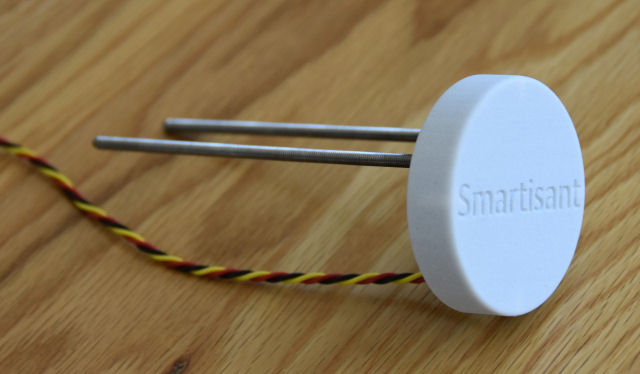
With the core functionality working as expected, the next step was to connect the Smartisant Soil Moisture Sensor SML1. The connections are explained in the SML1 application notes.
I'm using the GND connection but the supply to the sensor is connected to GPIO5 / D1 pin, so that the sensor can be turned on and off to reduce power usage when the processor is in deep sleep. The analogue output of the sensor is connected to the ADC0 / A0 pin. When enabled, this sensor is using just 2mA.
Battery Power
The microprocessor runs at 3.3V and has a minimum operating voltage of 2.58V and a maximum voltage of 3.6V, so a LiFePO4 battery is the best option for this type of application. I don't have a battery like this yet, so I'm using ones I have readily available.
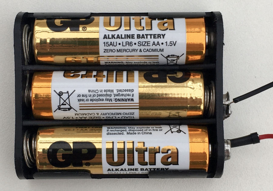
All my initial testing is being done with 3 GP Ultra AA batteries giving 4.5V. I will start testing rechargeable batteries later.
Lithium Ion Batteries
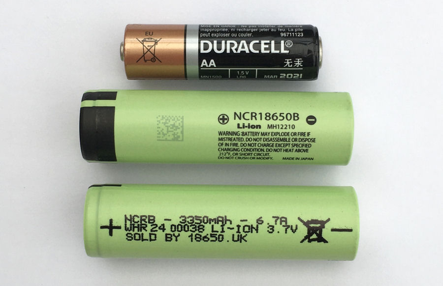
My preferred rechargeable battery option is the 18650 Li-ion battery. These are 3.7V batteries and I'm using the Panasonic NCR18650B which is unprotected and has a 3350mAh capacity and a 5A CDR.
Unprotected Li-ion batteries do not have an electronic circuit in the cell packaging and so they can have more capacity and current capability than a protected cell. Because my Li-ion batteries are being used in a tightly controlled use case and are being used outside, I don't need to use protected batteries.
The voltage on both my 18650 batteries on delivery was 3.52V.
Battery Holders
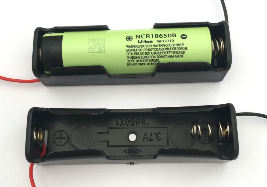
I'm using these plastic battery holders to enable easy connection of the batteries using a 2-way Molex connector.
Battery Charging
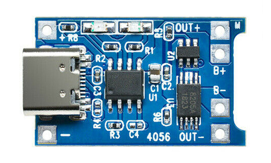
I'm initially charging my Li-ion batteries using this tiny USB-C TP4056-based charging modules. These are small enough and cheap enough to deploy next to each processor and battery.
Low Drop Out (LDO) Regulator
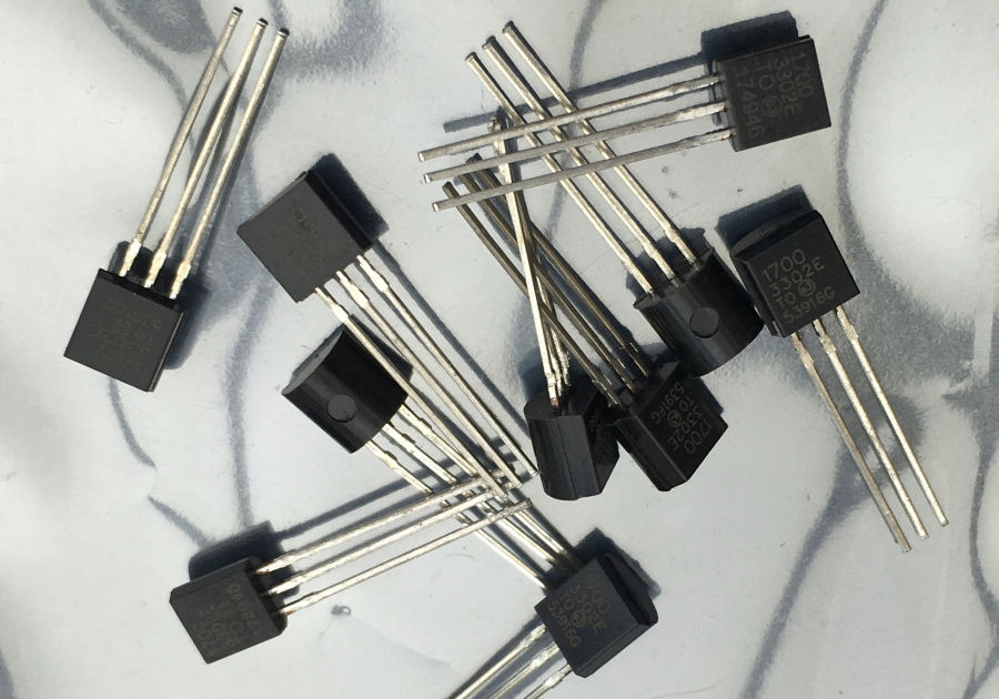
In order to limit the voltage supplied to the processor, I'm using a MCP1700-3302E Low Drop Out (LDO) regulator. In operation this draws just 1.6µA. The input voltage range is 2.3V to 6.0V. The voltage drop is 178 mV typically at 250mA load.
Another good alternative is the XC6206 3.3V LDO regulator and this also accepts input voltages up 6.0V too.
Visual Indicator
Sometimes, it's nice to get some kind of visual indication that something is operational. The 433MHz soil moisture sensors I'm currently using are a good example of this. It is comforting to see them flash blue when they send data back to the display unit.
At the risk of decreasing battery life, I'm planning to do something similar but, it can be disabled if need be. I'm using one of the spare GPIO pins (D2/GPIO4) to drive a green 3mm LED for a very short period of time, once the processor is awake and connected to Wi-Fi. This can easily be disabled in software if not needed.
Phase 2 Testing
Testing showed that we have both a heartbeat and sensor reading from the Smartisant Soil Moisture Sensor SML1 being sent every 3 hours. My technology abstraction and hybrid technology approach to smart home means that all the processor has to do is send some (encrypted) JSON of the form:
{"type":"Percent","zone":"Front Garden","object":"Front Garden Soil Moisture Level","value":"85"}
One thing to be tested is the behaviour when it fails to connect to the Wi-Fi. I'm going to put in false Wi-Fi credentials and test this scenario in more detail.
Another thing to be tested more thoroughly, is the Wi-Fi range. I've got excellent Wi-Fi coverage thanks to my BT Whole Home Wi-Fi but, I want to test this device when on battery power and at the far end of my garden.
Battery Reporting
The voltage divider is calibrated to provide 3.00V on the analogue pin with 4.50V on the supply line.
For now, the processor measures supply (battery) voltage and reports it in the form:{"type":"Voltage","zone":"Outside","object":"NodeMCU 1 Voltage","value":"3.72"}
and also reports battery level in the form:{"type":"Battery","zone":"Outside","object":"NodeMCU 1 Battery","value":"100"}
The battery percentage is calculated based on the voltage seen but it is a complex algorithm that will require further development because the available energy depends on different charging/discharging currents, temperatures and aging effects. It would be nice to include a local battery temperature sensor to help with this calculation.
Once I'm confident in the battery percentage is accurate, then only this will be sent back to my Home Control System in order to minimise the time the processor is awake.
Deep Sleep Power Usage
From my research, the ESP8266 processor typically uses about 0.3mA in deep sleep mode and in normal usage with Wi-Fi enabled, the ESP8266 can consume between 50mA and 170mA. The NodeMCU ESP8266 contains other components though. The 3.3V onboard voltage regulator draws at around 5mA and the USB to serial chip draws current as well.
My initial measurements for just my MCP1700 based power supply alone, show a current draw from the battery of around 9uA.
With just the NodeMCU ESP8266 connected, the current draw on start up was about 80mA. This dropped to 12.3mA on entering deep sleep mode. On subsequent wake ups, the current draw seen was as high as 100mA. So the NodeMCU ESP8266 isn't as low power a device as I'd hoped. This means the battery life is not going to be many months :-(
Phase 3 Build
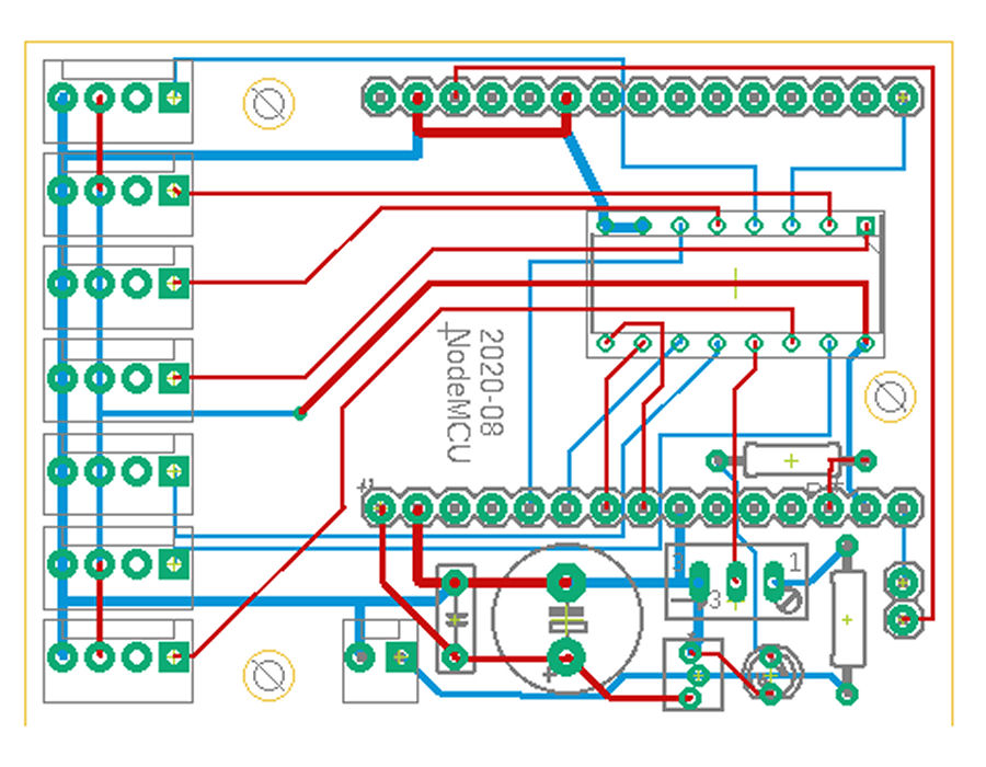
For this third and final phase, it made sense to design and produce a bespoke PCB for mounting the NodeMCU ESP8266 with the analogue input selection circuit, the voltage regulator and the battery charging circuit. This is now complete and has been uploaded for manufacturing.
I will also look at a bespoke 3D printed enclosure for the PCB, battery and solar cell. This will allow me to deploy remote soil moisture level sensors in various plant pots around my garden.
Temperature Sensor
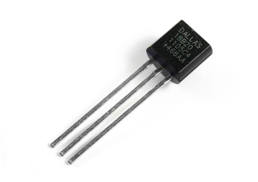
One option I'm investigating is the use of the Dallas 1-Wire DS1820 temperature sensor. These have a tiny stand-by current and use just 1mA typically when in use. There are plenty of spare pins and only one is required to interface this to the NodeMCU ESP8266.
This would help improve the accuracy of the remaining battery capacity.
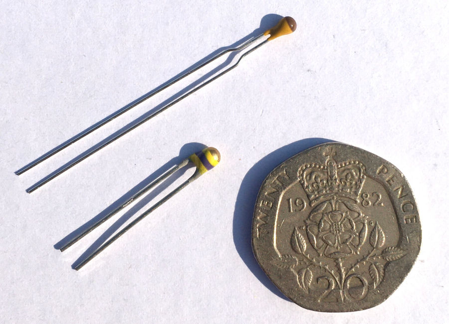
I decided against the DS1820 route initially as I already have the ability to connect many analogue sensors. I'm using a 10KΩ NTC thermistor instead.
Solar Battery Charger
The next part of this project requires a solar battery charger that can charge the battery whilst it is still providing power to the processor.
Phase 3 Testing
PCB
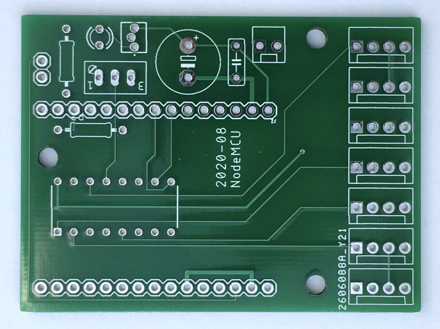
This is my manufactured PCB is just 62mm × 46mm.
Voltage Regulator
The first part built and tested was the voltage regulator and this showed that I had bought a duff batch of voltage regulators on eBay. They just got really hot very quickly :-(
Board
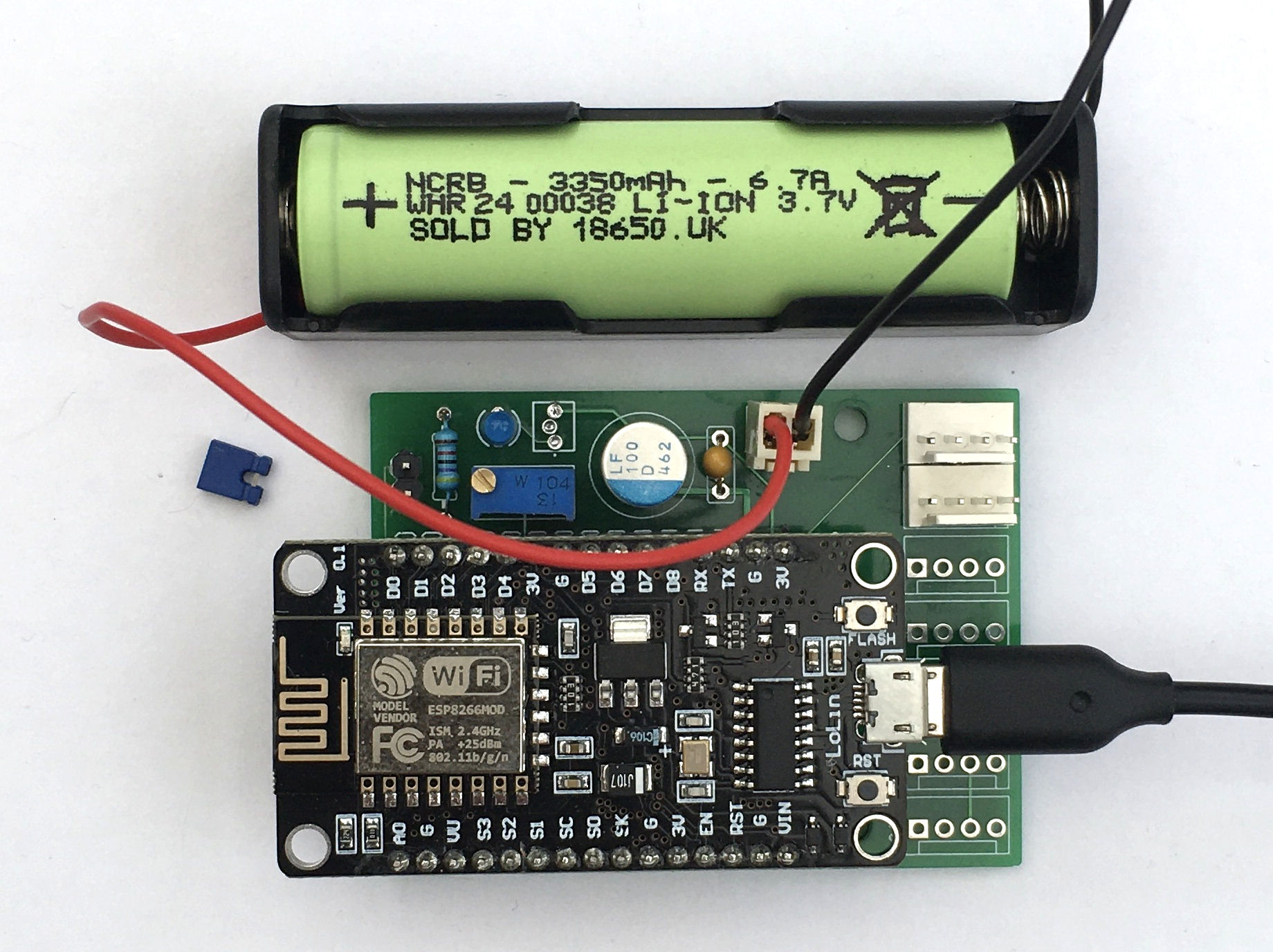
This is the PCB with all the components installed apart from the voltage regulator. I can test all of the other functions by running it on USB power. The (blue) jumper is to connect the right pins together, to enable wake up from deep sleep and has to be removed when programming the processor. The voltage divider is now calibrated to measure the battery voltage (0 to 5.0V dc) and the reporting of battery voltage and battery capacity remaining is working well.
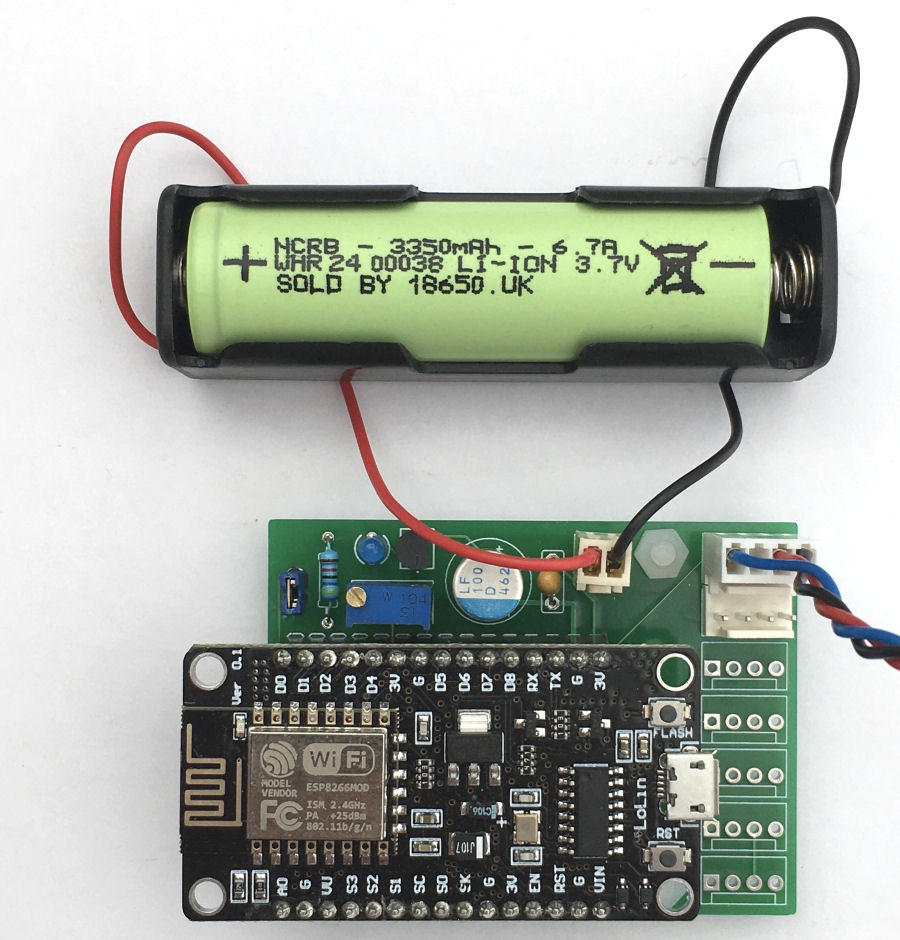
Installed a working MCP1700 LDO regulator and now I can start the battery life tests properly. The jumper is now also installed to enable the deep sleep mode.
Battery Charging
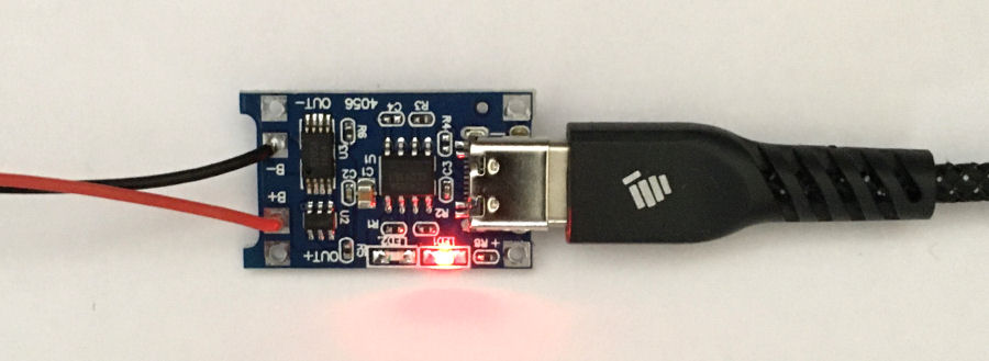
Connected up the TP4056-based USB-C charging modules. These things are tiny. The red light indicates that the battery is being charged. The initial charging took over 5 hours. A blue LED indicates when the battery is fully charged.
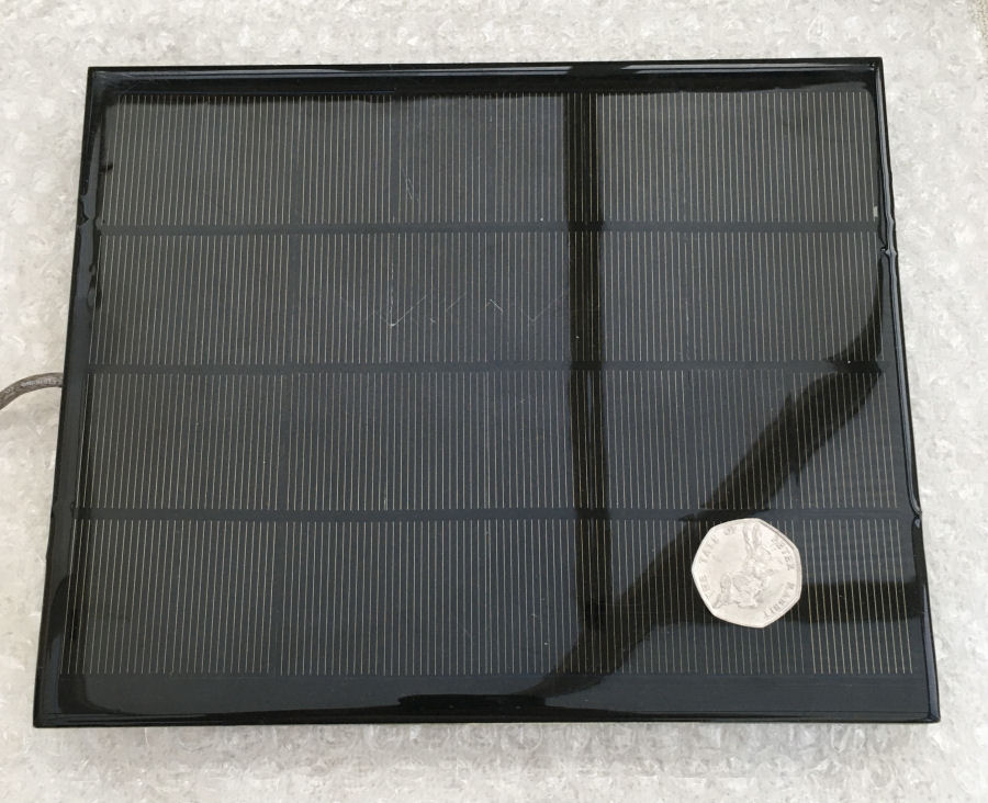
I had this 6V solar panel lying around and it has an LDO regulator feeding a USB port. When connected to the TP4056-based USB-C charging module, it charged up the battery from 40% to 100% in less than half a day.
Battery Voltages
The voltage on both my 18650 batteries on delivery was 3.52V. I monitored the voltage being put into the battery by the charger and it never exceeded 4.2V, which is what I would have expected. The voltage on the batteries (with no load) when fully charged was 4.15V.
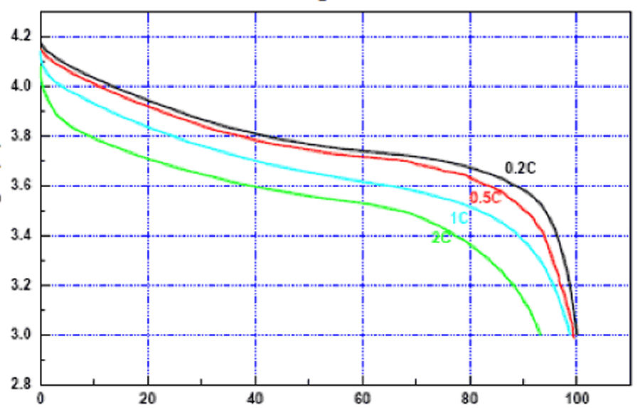
To translate the measured battery voltage to a percentage capacity remaining is not a simple process because the discharge curve is not linear. I'm not after super accuracy though and I will map a number of voltages to the 10% increments and 5% increments at the end of the curves. At the very ends, I can even go to 1% granularity.
I'm starting on the basis that 4.15V is 100% charged and that 3.4V equates to 0%. In practice, I would never let the battery discharge completely.
This gives me the following voltage levels for each percentage:
| Capacity | Voltage |
| 100% | 4.150 |
| 99% | 3.945 |
| 98% | 3.915 |
| 97% | 3.890 |
| 96% | 3.875 |
| 95% | 3.860 |
| 90% | 3.820 |
| 85% | 3.765 |
| 80% | 3.745 |
| 70% | 3.680 |
| 60% | 3.645 |
| 50% | 3.600 |
| 40% | 3.570 |
| 30% | 3.545 |
| 20% | 3.525 |
| 15% | 3.515 |
| 10% | 3.470 |
| 5% | 3.450 |
| 0% | 3.400 |
Thermistors

Using a matching resistor and thermistor, I was able to calibrate the input voltages seen to get a nice accurate reading. The main advantage of using a thermistor is that they are tiny and so they have a low thermal mass. This means they respond very quickly to changes in air temperature, making them ideal for Heating, Ventilation & Cooling (HVAC) and medical applications.
Examples & Use Cases
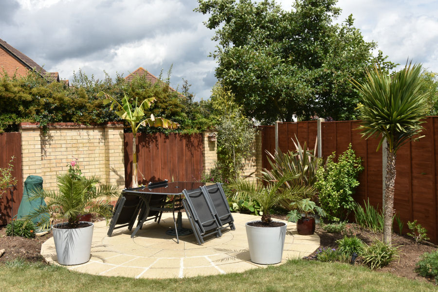
I have quite a few exotic plants around the patio at the far end of my garden and some of them are quite valuable. I plan to deploy a NodeMCU ESP8266 with several of my Smartisant Soil Moisture Sensor SML1s to report back soil moisture levels and let me know when they need watering. This is then due to be replaced by a fully automated irrigation system which is in development.
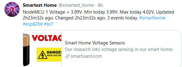
My contextual smart home occasionally tweets about the NodeMCU ESP8266 devices and the various sensors attached to them.
Summary & Learning
So far the NodeMCU ESP8266 has managed to deliver well when used with deep sleep mode and infrequent wake ups but, the power consumption is still too high to deliver the excellent battery life required. The main reason for this is that this particular processor features other components on the PCB and these increase the current usage in deep sleep mode significantly.
There are examples of people hacking the PCB, to disconnect the on-board voltage regulator and USB serial chip but, I don't want to go down this route. My focus is now on solar power to recharge the battery and other techniques that will help extend battery life.
I've used this evaluation to test with a Smartisant Soil Moisture Sensor SML1 but it could be used with a wide range of sensors, including a fuel oil tank level sensor.
The use of the CD4051BE IC makes the NodeMCU ESP8266 much more powerful and essentially gives it 8 analogue or digital inputs, or a combination of both. This means it can now also monitor battery state and report this back to my Home Control System. One battery powered processor at the end of my garden could now monitor soil moisture level in 7 plant pots using my Smartisant Soil Moisture Sensor SML1 :-)
With local solar battery charging, there is less need to extend the battery life and more advanced features could also be added. The goal is to never have to manually charge the battery at all.
This project has got me thinking about what else would be possible with this processor. I'm now looking at using the NodeMCU ESP8266 to do the following:
- To wake the microprocessor up, e.g a Smartisant Flood & Leak Sensor FLD1.
- Using this processor with permanent power to drive an OLED display.
- To wake the microprocessor up on mains power failure.
Updates
09/09/2020
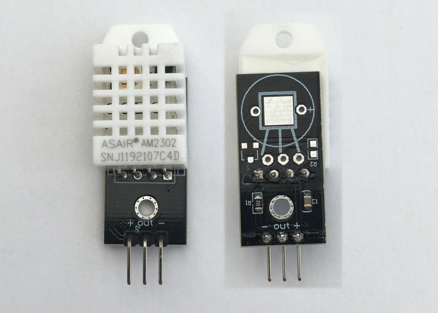
I started to look at how I might add a humidity sensor to this processor and the limiting factor was the 3.3V operating voltage. I bought a DHT22 sensor, which is a combined temperature sensor and a humidity sensor and works with a 3.3V supply.
Testing showed this works well, so I have updated my PCB to incorporate another 4-way Molex connector to support this sensor or a Dallas 1-Wire DS1820 temperature sensor sensor as they are electrically similar. Both required a resistor between the power and data pin and this also supports my switched power supply to all sensors.
Further Reading
- Running Wifi Microcontrollers on Battery by Thorsten von Eicken.


