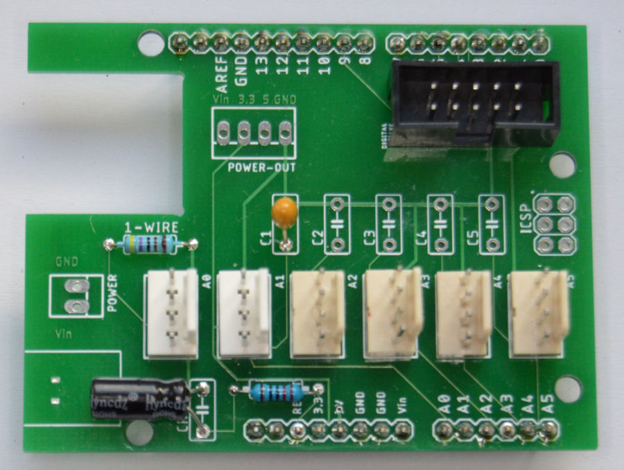
Arduino Smart Home Shield
In August 2020, I updated this shield to include even more functionality. It now exposed the I2C pins (on the Mega 2560) via a header, to make it really easy to connect things like OLED displays.

As part of my smart home building blocks approach to the smart home I have developed our own Arduino shield, to enable me to prototype and build new smart home services and features quickly and reliably.
Although this shield is primarily aimed at the Arduino Mega 2560, most of the functionality will also work with the Arduino Uno. The challenge with this latter device is the lack of memory though, especially when our encryption libraries are used for secure communications with our smart home.
An important aspect of this shield is that I don't have to fully populate it with components. I only install the parts required for each specific application and it is very easy to add more components later if required. This makes it an extremely cost effective way to develop my smart home.
Connectors
We have used our standard set of connectors and pin designations on this header.
Features
The first thing this shield includes is an RC delay circuit to allow more time for Ethernet shield to boot up. This is achieved with a 220uF capacitor and a 220Ω resistor.

The shield exposes the analogue inputs (A0 to A5) via 4-way Molex connector (along with +5V and GND). These can be used to connect a wide range of sensors but they can also work as digital inputs. The shield has a provision for a 0.1uF capacitor on each input, which improves stability when reading voltages that change slowly.
It includes provision for a 4K7 resistor on the A0 pin, which is our default way to connect Dallas 1-Wire temperature sensors.
The shield exposes pins 2 to 9, along with +5V and GND, via a 10-Way DIL connector. This allows us to connect our 12V input board, output boards and many other things. It is essentially and 8-channel I/O port.
The shield also exposes Vin and GND via a 2-way Molex connector, to enable easy connection of power. Typically we supply 8.5V dc via these pins.
Production
The PCB was designed using Autodesk Eagle and we then had a large number of these boards manufactured for us by JLCPCB at a very low cost for each board.
Connectors
Summary
This shield is now a Smartisant product and available in the Smartisant Store.


