8-Channel High-Power Output Board OP3
I've been using lots of digital output modules to control 12V lighting and devices but, most of these use 'low side switching'. This can be an issue, where you use a common ground, so I wanted to build a board that utilised 'high side switching'.
Design
As with a lot of my output boards, I'm using quad opto-isolators to provide electrical isolation. The input stage is typically driven from a 5V signal from an Arduino and is fed via a 1KΩ resistor, to limit the input current.
The output stage of the opto-isolator then provides a 12V dc feed to the base of the power transistor via a 1KΩ resistor, to limit the base current. In this design, I'm using the FQP27P06 P-channel MOSFET to do high side-switching. This means the +12V line to a load is actually being switched on and off. This makes a lot more sense in certain smart home applications because you can then use a common ground.
The PCB was designed using Autodesk Eagle software. We deliberately didn't use surface mount components, as the connectors are actually the largest parts on the board.
PCB Design & Manufacturing
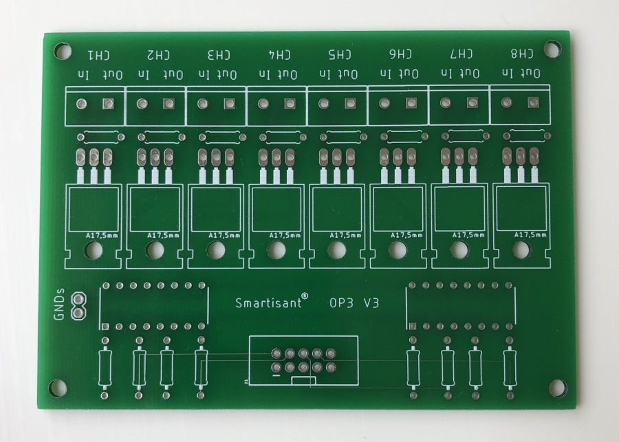
This is V3 of the PCB.


