Bicycle Hub Dynamo USB Charger
The objective of this project is to allow a SON hub dynamo to be used for both lighting and charging of 3rd party devices, such as a Smartphone. These hub dynamos output about 3W of power, so they can't be used for fast charging of Smartphones but still provide a useful mechanism to charge a device whilst on the move. The limited output of the hub dynamo means they can't be used for charging and lighting at the same time.
Design

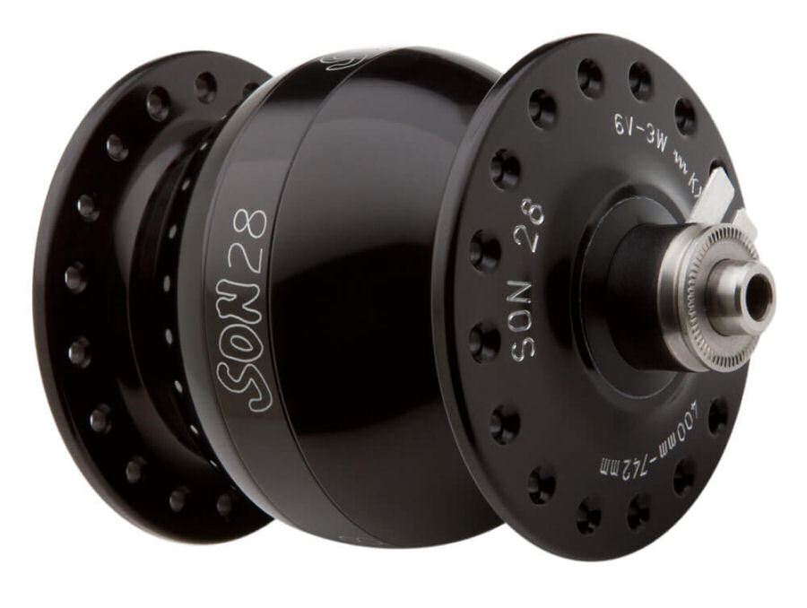
With no load, my SON hub dynamo puts out an ac voltage that exceeds 16V. The voltage output from the dynamo drops off as greater loads are applied and typically it will supply 6V at about 3W maximum power.
This power is fed to a 3-way on-off-on switch, to divert power to the lights, charger or have both switched off.
Voltage Rectifier
As my SON28 dynamo outputs an ac voltage, a bridge rectifier is needed to convert this to a dc voltage supply required for the USB charger and to drive the LED lighting. The diodes in a bridge rectifier introduce a voltage drop (0.7V for ordinary silicon p-n-junction diodes and 0.3V for Schottky diodes). Because the dynamo output ramps up with speed, it is key that we don't introduce too big a voltage drop with the diodes in the rectifier circuit. A bigger voltage drop, means the bicycle will have to go faster to reach full output.
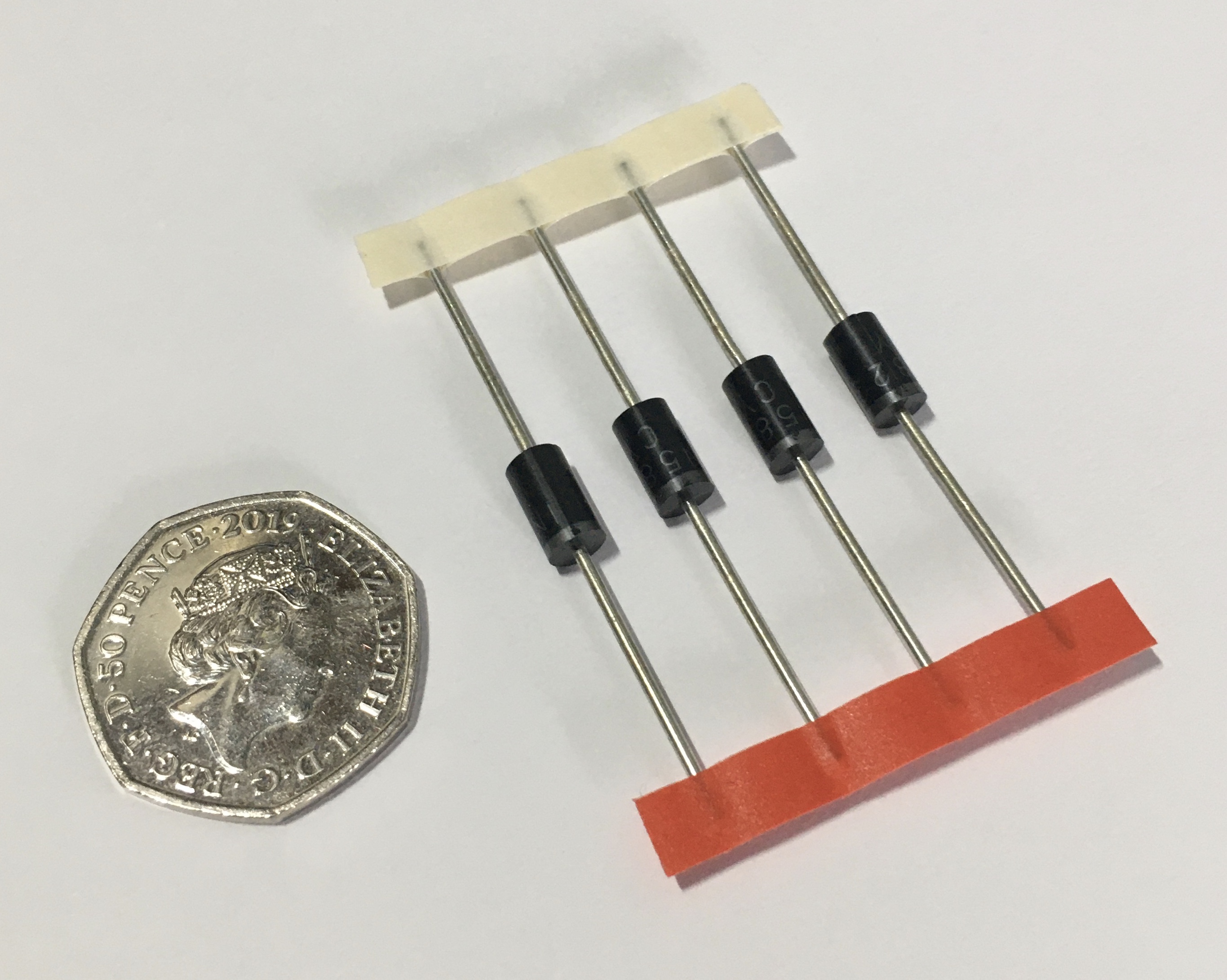
I am using the 1N5822 3A Schottky diode because it has a low forward voltage drop (0.3V) and can handle currents up to 3A.
My rectifier diodes are sealed in some heatshink sleeving and sit in-line in the power cable.
Voltage Regulator
For USB charging a 5V regulator is required. Like the diodes in the bridge rectifier, voltage regulators also introduce a voltage drop. Typically this can be 2.0 to 2.5V and this is simply too big for this application. Fortunately, you can get 'Low Drop Out' or LDO voltage regulators, which introduce a much lower drop into the circuit.
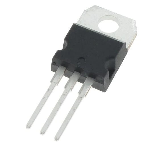
I'm using a Micrel Semiconductor MIC29300-5.0WT (PDF datasheet). This is a 3A fixed voltage (+5 Vdc) with a very low drop-out voltage, typically around 250mV. This regulator can handle input voltages as high as 26Vdc, so it will be fine if connected to the hub dynamo with no load attached.
For stability and minimum output noise, a capacitor on the regulator output is necessary. The value of this capacitor is dependent upon the output current. With the MIC29300 a 10µF capacitor is recommended.
The MIC29300 regulators are specified between finite loads. If the output current is too small, leakage currents dominate and the output voltage rises. The MIC29300 needs a minimum load of 7mA and this can be achieved by placing a 680Ω resistor across the output. This wastes a bit of power but, ensures the regulator works within its specification and won't damage any devices attached to this circuit.
The MIC29300-5.0WT 'tab' in a TO-220 package is also the GND pin.
iPhone Charging
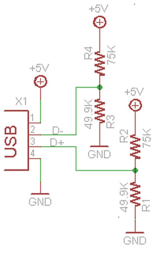
Charging iPhones via USB ports requires the iPhone to 'see' the right resistances across the USB port pins. If this network is not present, an iPhone will not charge. The resistor value tell the iPhone how much current it can draw too. Given that the hub only outputs 3W, we can only ever expect the iPhone to charge at the standard 500mA 'slow' charging rate, so we use this arrangement of resistors to signal this.
This network of resistors will be optional. In practice, I'm using 51KΩ resistors as these are the closest I can get to 49.9KΩ.
PCB Design
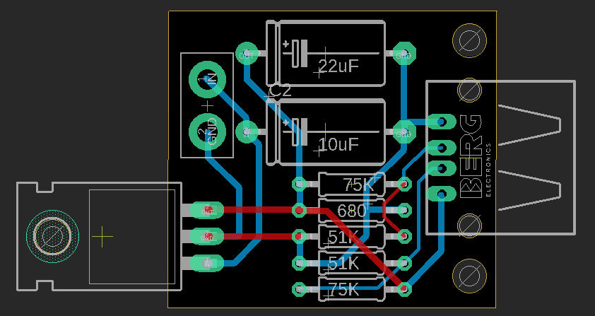
I've designed a custom PCB using Autodesk Eagle for this application and will get it manufactured. This will greatly improve reliability. The PCB is just 38mm × 28mm and take the rectified voltage from the hub dynamo (2 wires), via the switch.
The reason the regulator runs off the PCB is because it folds over to mount to a heatsink that sits above this PCB. The two 3mm holes are to hold this heatsink in place.
Enclosure
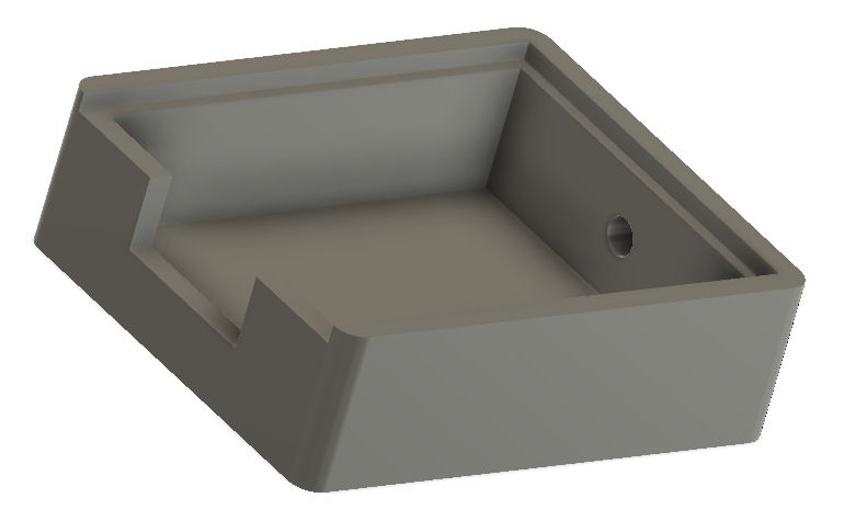
I've used Autodesk Fusion 360 to design and 3D print an initial enclosure, which is 42mm (L) × 36mm (W) × 13mm (D) and accepts a 40mm × 32mm aluminium 'lid' (1.5mm thick), to act as a heatsink. The electronics, will be resin encapsulated to make them fully waterproof.
Build
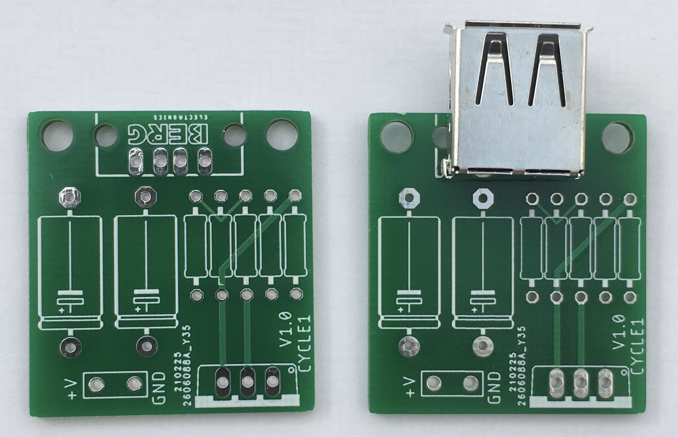
The PCB and parts have arrived, so I've built one up for testing.
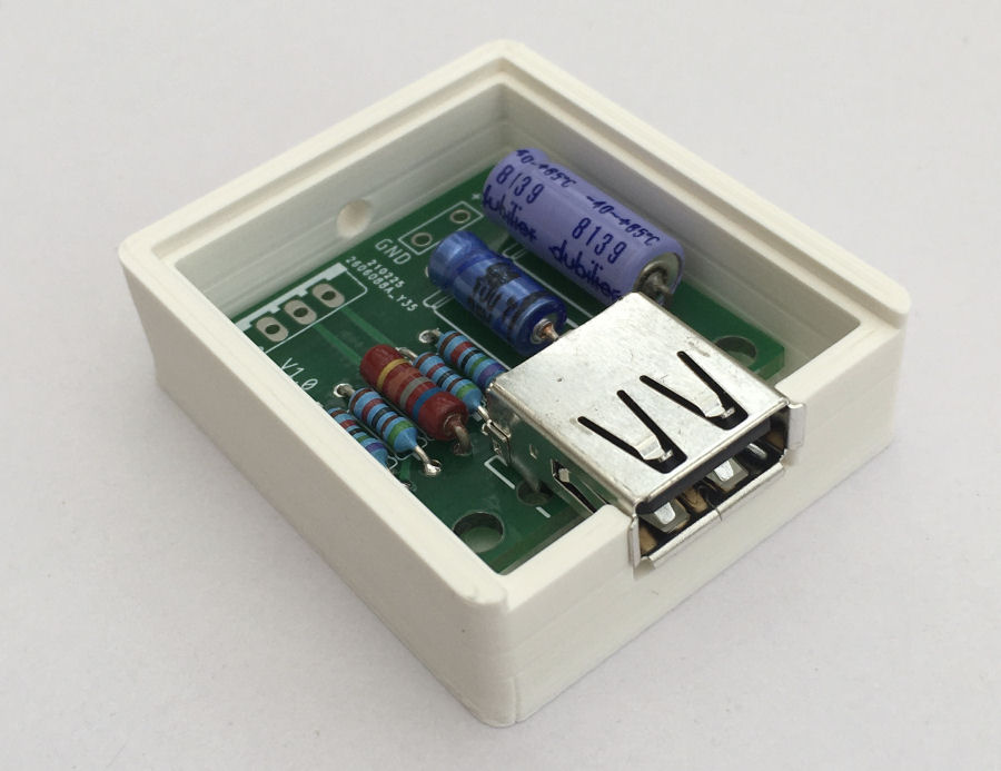
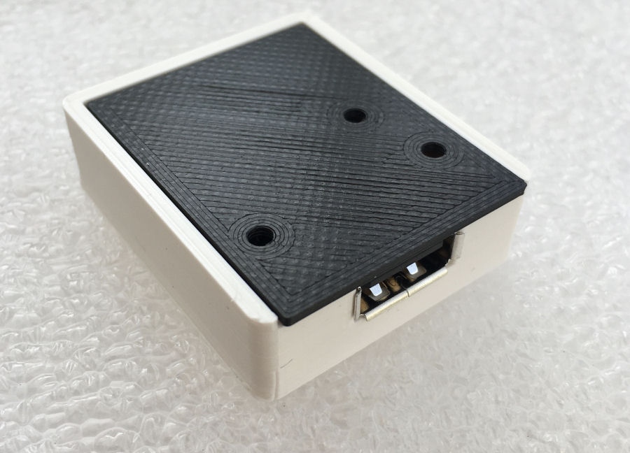
The 3D printed enclosure is 42mm (L) × 36mm (W) × 13mm (D). I've printed it in white here but, it could be pretty much any colour.
Since this item was printed, I've modified the power cable entry hole slightly. It's now two separate 2mm holes.
To test the size of the heatsink and the hole positioning, I 3D printed one. This worked perfectly, so my next job is to cut one from some 1.5mm aluminium sheet.
Testing
I've been running this circuit on my current bike for over 10 years now, so I'm confident that it works reliably. The main testing left to do will be testing this new PCB design and packaging.
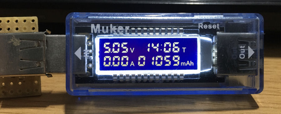
To test my circuit, I'm using a Muker TM-103 USB multimeter and charge detector. This allows me to check the USB port voltage and power being supplied to the device being charged. It's a very handy bit of testing equipment for projects like this.
- Test that the USB outputs a steady 5V with a 6V dc input to the regulator circuit. The voltage will drop slightly below 5.0V and this is normal behaviour.
- Test the current being supplied using the Muker TM-103 and check the regulator IC doesn't get warm. It does get a little bit warm, so I'm going to add a heatsink to my design, to be 100% confident it won't overheat even on the hottest of days.
- Test charging works using a range of Android phones.
- Test charging works using a range of Apple iPhones. My iPhone 6S charges fine at 4.7V and 0.7A.
- The final test is to check the charging circuit with a wider range of USB devices. This will include USB battery packs and a GoPro 6 camera.
Summary
This small charging module should allow charging of a wide range of devices via a USB port, powered from a hub dynamo. This is particular useful when touring by bicycle or when simply out on a day trip.
I've been asked about making this device for a few friends, so I'm building this with a limited production run in mind. The cost will be less than £20 including postage in the UK.


