Connected Vehicle Project

This project describes the hardware and software I have used to support my initial research on smart home connected vehicles. It's the first part of a series of projects, to research and trial some ideas and understand what technology adds real value when the smart home and your vehicles can exchange information.
There are four adults in our household currently, with five cars between us. My 'children' are insured to drive at least two of the cars, my wife three of them and myself all of them. This means car tracking cannot be achieved by simply tracking people via their personal devices (e.g. smartphones). There is also more context and insight to be gained by tracking the vehicles in addition to the many techniques I'm currently using to track people.
Background
I'm aware of various related 3rd party activities in this space and modules that plug in to ODB ports are very popular. Unfortunately, only the more modern cars have ODB1 or OBD2 ports. Projects like OVMS are also OBD port based.
I'm going down a bespoke route for now, albeit one based on open-source hardware and my own software. This will allow rapid prototyping and testing at very low cost and will allow me to identify and refine my requirements. The key difference with my approach is that it's not really about the vehicles. I'm more interested in what value they can add to my contextual smart home.
Design

A key requirement of this project is that it works with any car. We have a wide range of cars including a new Mazda CX-30, a 2018 MX-5, a 1990 Eunos Roadster and my own Fisher Fury R1 kit car. Each presents a different challenge in terms of technology integration and wiring. So I'm focussing on a solution that works with all of them initially.
Power
A key requirement of my design is that it takes no power from the car battery when it is not doing anything. This is really important as some of our vehicles are not used for fairly long periods of time and I don't want to drain the battery. My Fury R1 also has a tiny 11Ah motorcycle battery to save weight.
To achieve this my design has two connections to the car's power, one via the ignition switch and one to a permanent power connection via a relay. This means that when the ignition is turned on, the device will power up and enable the relay, ensuring power is not cut until it is finished what it needs to do. When the ignition is turned off, power is maintained to my PCB and this can be detected and reported as an event. When the ESP8266 has finished what it needs to do, it can switch off the relay and cut all power to itself.
This is important because it means my contextual smart home can tell the difference between a the vehicle being stopped on the drive or being driven away, out of Wi-Fi range.
Networking
Initially, my focus is purely on Wi-Fi connectivity, to keep things simple and to test the key concepts. The next iteration will involved other, more advanced networking and communications. 2.4GHz Wi-Fi is fine for now though. It has good range and my cars connect to my home before it has come to a stop up onto my drive.
Sensors
One of the inputs to the processor is a sensor that detects the ignition being switched on and off. Because this is a 12V signal, it is interfaced via an optocoupler, to translate this to a 5V signal.
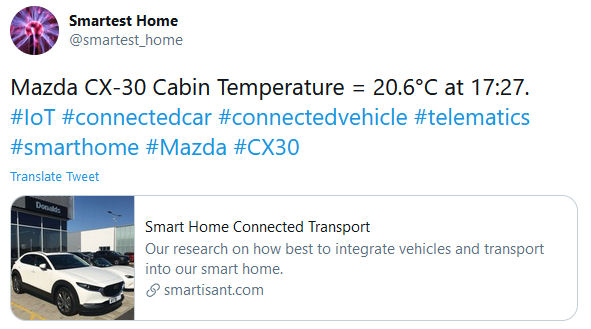
There is an on-board Dallas 1-Wire DS1820 temperature sensor, to measure the 'cockpit' temperature inside the vehicle. Occasionally, my @smartest_home will tweet this.
Implementation
Power
Getting access to permanent power and a switched ignition feed is fairly easy but, it depends very much on the car. In a car like my Fisher Fury R1 kit car this is easy as I built the wiring loom for the car from scratch. For the Eunos Roadster it is also quite easy as feeds for things like the cigarette lighter are switched via the ignition and this is true of most modern cars. Sometimes, I need to run an additional wire for the permanent power feed and this is always done using a 3A in-line blade fuse holder.
PCB V1.0
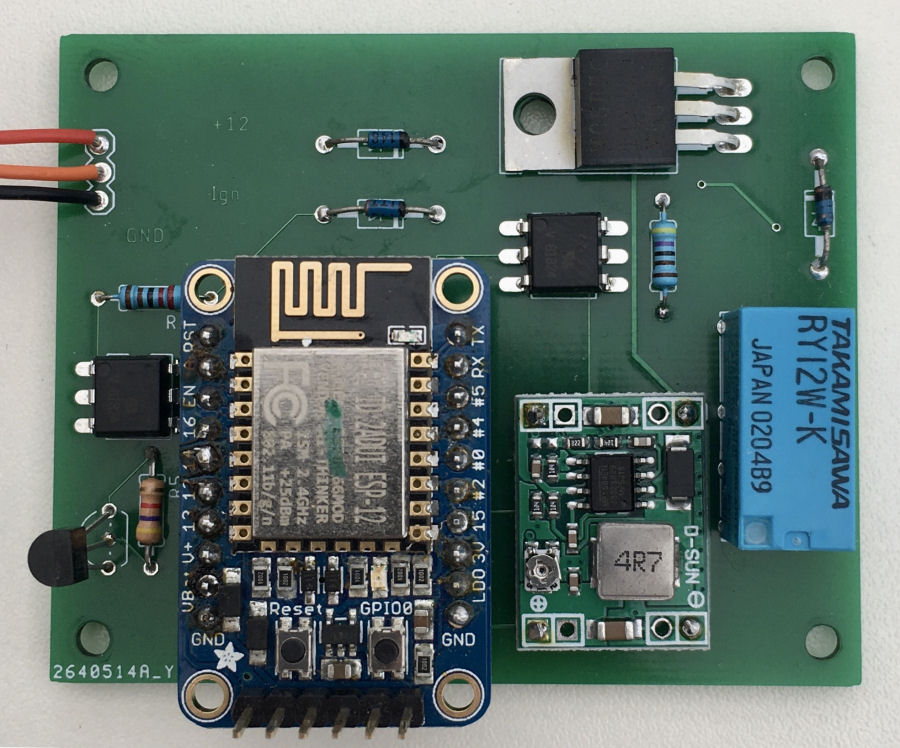
To simplify the installation of an ESP8266 processor in a car and to handle the power management and connected sensors, I have designed and manufactured my V1.0 PCB using Autodesk Eagle.
This PCB has a permanent power feed and a power feed switched via the ignition. Applying power via the ignition feed, will enable the relay and connect the permanent power feed. A TIP120 power transistor is used to control the relay. The 12V power is fed into a dc-dc convertor to deliver the required 5V power to the Arduino.
An opto-coupler is used to sense ignition power and the PCB also supports a DS1820 temperature sensor.
Software
The ESP8266 is always looking for my home Wi-Fi network and will connect to it when it is in range. It keeps track of how long it has been running, so it knows if it is already home or has arrived home at the end of a longer journey. The code is basically a state machine that uses the following states: BOOTUP, STARTUP, CONNECTED, DISCONNECTED, RECONNECTED, SHUTTINGDOWN, SHUTDOWN.
Smart Home Integration
Each vehicle is part of my contextual smart home's models and each one is essentially a mobile zone. This means all of the sensors and things like occupancy are inherited from my smart home, including all of its common capabilities.
Each Arduino installed in or on a vehicle, connects to our home Wi-Fi network when in range and once connected, can send events using my smart home's unified communications protocol.
Summary
Having the smart home track vehicles means that it has a lot more useful context and can do some very clever things, to improve the smart home user experience. When cars are linked to one individual (e.g. my kitcar is only driven by me), the the smart home can provide a personalised user experience.

My @smartest_home sometimes tweets when a vehicle has been started.
At night, this will extend the time the drive light stays on and will keep extended this time, whilst the car is still on the drive.

When my contextual smart home spots cars arriving home or knows they are still on the drive, it can do useful things like turning drive and porch lights on and keeping them on whilst the drive is occupied. It could also open automated garage doors, knowing which cars go into which garage.
It is also possible to link cars arriving home to the front door lock and unlock it automatically.
Because this is part of the wider context of my contextual smart home, it can also let me know when people or cars arrive home, using a notification or voice announcement if I'm already at home. This is addition to the context from personal devices like smartphones.
This is only my first project in this space, to understand what's possible and useful. I'm looking at other networking technologies with longer range and even greater legacy integration with my vehicles.
Version 2
I've now started to look at the next version of this project. This will incorporate the following features:
- A switch to allow easy change over between my development and live smart home.
- I will add an LED to indicate successful Wi-Fi connectivity.
- A rechargeable 18650 3.7V Li-ion battery, which will be charged when the ignition is on using a relay to change over the battery connections.
- The processor will go into deep sleep mode and use local battery power when the ignition is off, to allow it to perform various checks and measurements at regular intervals. The assumption is that the battery can last at least 3 months between charges.
- The processor will monitor and report the cars battery voltage.
- A GPS module will be used whilst the vehicle is in motion.
- Data logging and data dump via Wi-Fi on connection to the smart home.
- As well as Wi-Fi, I'm going to look at other networking technologies.
- All sensors connected via 4-way Molex connector, to allow eaasy installation and changes.
- Cockpit humidity sensor.
I'm going to need more analaogue input ports than standard ESP8266 based processors provide, so I'm going to go down the route I used with my NodeMCU ESP8266 project, which used a CD4051BE IC to allow 8 analogue sensors to be connected to the one analogue input.


