Smart Water Shut-Off Valve Project

This project aims to take a standard 'off the shelf' 15mm ball lever shut-off valve and make it smart. This project could also be used on 22mm valves as well though. The thinking is that in our next home I could install these types of valves and then add the 'smart' bits myself. It does assume there is space around the valve for the parts described in this project though.

My thinking is that you can make a dumb shut off valve smart and that you don't have to do this from the outset. So long as you use this 3D printed valve mount to locate the dumb valves in any home, the smart elements can be added later. The valve will also continue to work manually. The mount has two 4mm holes, to allow it to be fixed to a surface.
To make the valves smart, I'm using an Arduino, to drive a stepper motor. In my case, I'm using Ethernet networked Arduino processors (for maximum reliability) and a local 12V dc power source. This could be a protected power source if required.
Design
Key Requirements:
- Be able to control the valve securely over an IP network (using my unified communications protocol).
- Be able to operate the valve by hand, in case of power cuts or other issues.
- Be able to operate the valve using simple push buttons on it.
- Be 100% sure that the valve is open or closed, using end-stop switches to validate the state and report it.
- Report errors if the valve does not open or close within the expected time.
Other Requirements:
- Be able to connect a Smartisant Flood/Leak sensor to also check for any leaks in the proximity of the valve(s).
Valve
For this project to work well, I'm going to need to use a high quality lever ball valve, so I'm using an 'off the shelf' item made from DZR brass as these have a smoother and easier action. It was bought from Screwfix and cost £13.07.

The first thing I did with the valve, was to remove the handle. This features a sliding locking tab which simply gets in the way. The handle is held on with an (imperial) ¼" nyloc (requiring a 12mm spanner to undo it). This then reveals the shaft, which has flats on both sides and is 10mm long.
I'm keeping the handle because it is going to be modified and refixed later, to enable manual operation.

Top view of shaft. The valve is quoted as being a quarter turn (90º) from open to closed.
Motor

The plan was to use a standard dc geared 12V motor or a high power stepper motor to rotate a small HDT5 profile 14-tooth cog. Initially, I'm going down the stepper motor route as it gives me greater control and enables the motor to be switched off, to allow manual operation.

I'm using a readily available stepper motor.
This Nema 17 Stepper Motor is powerful (holding torque is 59Ncm 83.6oz-in) and measures 42mm × 42mm × 48mm and weighs 376g.Motor Mounting Plate

The stepper motor mounting plate has mounting holes for two LEDs and two momentary push buttons on it. An orange LED is lit when the stepper motor is enabled and the lever should not be turned manually. The red LED indicates an error, such as the valve being stuck.

This is the 3D printed stepper motor mount viewed from below.

This is the 3D printed stepper motor mount viewed from above.
Transmission
The motor will be connected to the valve using an HDT5 profile drive belt, to drive a larger cog, effectively providing more torque to move the lever. These belts are really strong and are often used in electric scooters and skateboards.
Motor Cog

I've designed my own 12-tooth drive cog for the stepper motor.
Valve Cog

The valve cog has 50 teeth and was designed using Autodesk Fusion 360. There is a great guide to creating a HTD timing pulley in Fusion 360 available. It has a slot for the handle to sit in, to help grip the valve shaft.
The valve cog actually serves a number of functions:
- It fits on the profiled valve shaft and enables it to be rotated.
- The cog provides a mounting slot for the handle, to better transfer torque from the handle to the cog.
- It has some flat baffles on the underside that activate the micro switches.
- It has a skirt to stop the drive belt falling down and off the cog.

To make it easier to 3D print, I've designed the valve cog in two parts that simply bolt together. The lower part has the vertical baffles to operate the micro switches.
Local Processor
All the local logic and control will be done using an Arduino Mega 2560. This powerful small computer will be able to do all the control, messaging and logic for several shut off valves and still have capacity for many other features. I use them a lot in my contextual smart home and they are incredibly reliable also very secure.
Stepper Motor Control

To interface each stepper motor to the Arduino, I'm using an A4988 microstepping driver for bipolar stepper motors. This device makes controlling stepper motors really easy and I can control a stepper motor using just three output pins on the Mega 2560:
The stepper motor is using full step mode, to maximise the torque.

My design uses end-stop micro switches to detect when the valve is fully open and closed. When these are activated, the changes in state will be reported back to my Home Control System.
The switches are fixed to the top of the mounting plate and actually reside inside the hollow cog. The hollow cog features vertical baffles at 90°, which operate the micro switches.
Buttons

Two momentary buttons will be located on the housing to enable local control. The blue button opens the valve and the black button closes it. Both buttons also provide kitchen occupancy information to our Home Control System when pressed.
Smart Home
This project is just one more thing that can easily be connected to my contextual smart home. My Home Control System models the following items:
- Water Shut Off Valve - Open or Closed
- Water Shut Off Valve Open - A momentary button
- Water Shut Off Valve Close - A momentary button
- Outside Tap Shut Off Valve - Open or Closed
- Outside Tap Shut Off Valve Open - A momentary button
- Outside Tap Shut Off Valve Close - A momentary button
My smart home is configured to automatically shut off the outside tap valve after it has been open for more than 3 hours.
Build
Valve Mounting Plate

The new valve plate design installed with the mount.
Motor Mounting Plate

The motor mounting plate can be spaced off from the valve mounting plate to tension the drive belt but, I've designed it to perfect tension the belts I'm using without any spacers.
Switches

The end-stop switches are bolted to the valve plate using 2mm bolts.
Prototype

With all the prototype parts assembled, this is the working smart shut off valve.
Leak Sensor
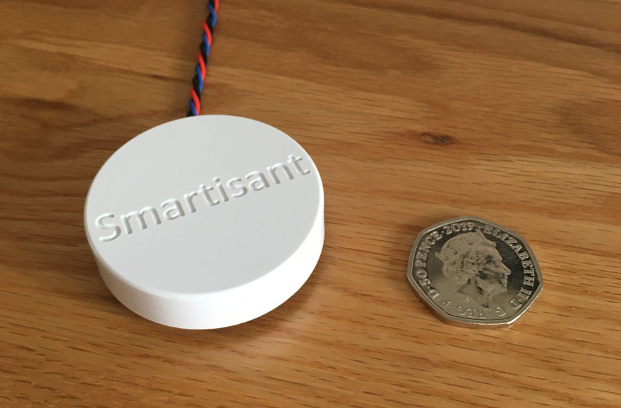
I have developed the Smartisant flood/leak sensor for exactly these types of applications. It is a low-cost, extremely reliable sensor for new builds and can also be retro-fitted into existing buildings. It is easily interfaced to many things including legacy alarm panels and our own contextual smart home.
Electronics

To make it easier to connect up the stepper motor and other parts to the Arduino, I have developed a bespoke PCB.

This is the built up PCB with components.
Arduino Code
I have a library of Arduino code I've developed over my many years doing smart home and this project re-uses much of it. This includes code for my smart home unified communications protocol and for sending encrypted events to my contextual smart home.
For each valve, I'm using three output pins per motor (direction, step and enable) and one for the error LED. The stepper motor driver 'enable' pin is active low, so this is directly connected to the green LED. Four input pins are used for the 2 micro-switches and the 2 push button switches.
The arduino code for each shut off valve is basically a state machine the valve is always in one of the following states:
- Closed - as indicated by the micro switch
- Opening - Follows 'Closed' stated.
- Open - as indicated by the micro switch
- Closing- follows 'Open' state.
- Unknown - Determined based on timing how long the valve was neither 'Open' or 'Closed'.
For the 'Opening' and 'Closing' states the motor is enabled in the right direction. If moved manually, the time taken to get to 'Closed' or 'Open' state is measured and if the valve is left partially open, the arduino will report an 'Unknown' state.
In Use
My shut off valves communicate directly with our contextual smart home using a unified communications protocol and it also models valves and all their characteristics. This means that they inherit all of our smart home's common capabilities.
Notifications
All state changes generate notifications to my smartphone.
Voice Announcements
I don't normally use voice announcements with valves as they can be a bit annoying for other family members. If there is an error or a valve is stuck, they will generate one though.
User Interfaces
To align with our smart home methodology on delivering a great user experience, our smart home exposes a number of user interfaces to control these shut off valves:
- I always try to enable a manual over ride and these valves are no exception. I have left the lever in place, to enable it to be operated by hand. Changes in state will be reported back to my @smartest_home.
- I have enabled local push button switches on each valve to enable them to be easily opened or closed.
- People can also make requests to open and close the valves, where permissions allow. These can be made via various interfaces inside and outside our home, including by web app and my smart home artificial intelligence capability.
Further Reading

My @smartest_home will tweet when these smart shut off valves are operated.


