12V DC Uninterruptible Power Supply (UPS)
This project provides a secure and reliable 12V dc power feed to supply our Home Control System, Internet modems, routers, hubs and other key security systems in our smart home. This is a project that has been running faultlessly in our smart home since 2010.
Design

I didn't really need to design or build much for this project as the required hardware already existed in the form of the picoUPS-100 board from mini-box.com. I bought mine in the UK from linitx.com.
The picoUPS-100 ensures uninterrupted power for electronics by automatically switching between a 15-18V DC input source and a lead-acid battery. The switching between the power sources is instantaneous, allowing a smooth and uninterrupted device operation. The picoUPS-100 also has a built-in, two-stage battery charging circuit and has been specifically designed for uninterruptable small/medium power PC operation, where 'always on' operation is required.
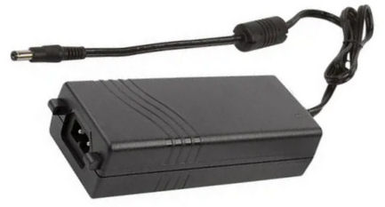
My design uses a high-current, mains-powered PSU to feed this circuit board. This will provide the required 16-18V DC power input and is rated at 8A continuous output. The voltage from this PSU is monitored to allow my contextual smart home to know if mains power is present and to be sure that the PSU is working as expected. It also monitors the temperature of this PSU.
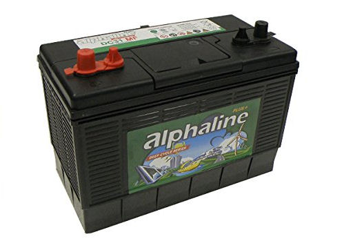
A large deep-cycle lead-acid battery bank is used to provide power backup. Assuming I only discharge it to a minimum of 40% capacity, this will keep the main Home Control System devices and components running for approximately two days.

My Home Control System monitors the battery voltage and will send a notification if the voltage drops below a certain level. Occasionally, my @smartest_home will tweet about the UPS battery voltage.
One feature lacking from the picoUPS-100 is the detection of a low battery charge state and automatic disconnect to protect the battery from total discharge. My smart home also monitors the battery voltage using one of the analogue inputs on an Arduino (with a suitable resistor divider). Once 12.6V (typically 40% of capacity) is reached the Home Control System will automatically switch off, removing the only significant load attached to the output.
This board doesn't provide the required 12V DC regulation. The power supply used outputs a voltage of 16.3V, which is too high to feed our 12V PC and the other core components of our smart home. On power failure the lead-acid battery will output voltages around 13.8V which is OK but, still higher than I would want.
Voltage Regulation

To provide a 12V regulated output I am using another of-the-shelf piece of hardware. This bit of hardware can actually support quite a wide set of features and functions but, as it is shipped it provides a regulated 12V output from an input voltage ranging from 6V to 30V.
This device could be connected directly to a 12V battery bank and can easily handle the voltages that would arise during battery charging.
Power Distribution
I used standard automotive electrical components for low voltage power distribution. 6.3mm blade connectors are typically used. The regulator +ve output is passed through an 8-way blade fuse box. This enables a separate fuse for each powered device or network and ensures the whole system cannot be bought down by a short in one power output. Most are on a 1A fuse but the mini-ITX PC uses a 3A fuse. The ground is distributed via a 6-way spade terminal block. The power cables between shelves are over-long, to enable them to be pulled out and worked on.
As well as colour coded wiring, I have also added wiring idents (numbers) to each wire installed in the 19" cabinet. This makes it much easier to test and fault find, should I ever have a problem.
Earthing
I have got to say a few words on earthing because it is important. The above system is earthed through the mains PSU used and throughout the rest of the design and installation the UPS ground or 0V line is assumed to be earthed. I make no assumptions about any other power sources and devices that are not connected to this line and if if doubt, optical isolation is used. At no other point do I connect the 0V power rail to earth in our home.
In Use

Occasionally, our @smartest_home will tweet about the UPS PSU temperature.
Occasionally, our @smartest_home will tweet about the UPS battery voltage.
Summary
- Some form of UPS is essential for any serious home automation system. The UPS not only protects the Home Control System processor from power failures but also protects it from damaging power surges.
- The UPS needs to provide power to all safety and security critical components. In our installation, this includes all sensors, PIRs, alarms, etc and essential IP-network components such as a switch and IP cameras.
- This project has worked flawlessly since 2010.
Updates
March 2012

This month I replaced the old (second hand) UPS battery with a new 125Ah deep-discharge battery. This one weighs 23Kg. This new battery was delivered with an output voltage of 12.80V whilst not connected. When connected into our UPS, it charged up fully over a period of over 3 days. When finally charged, the voltage across the battery was measured at 13.48V (when not charging).


