Smart Home Relay Board
The success of my HVAC controller board got me thinking that the relays used are a simple and cheap way to deliver smart home control of mains powered devices and appliances. So, I thought I would design a simple, single-channel relay board that can work with all my other smart home building blocks.
The object of this project is simply to provide a cheap and reliable way to control high-current, mains-powered (240Vac and up to 10A) appliances and lighting, fully integrating them in to the smart home and allowing intelligently control.
Design
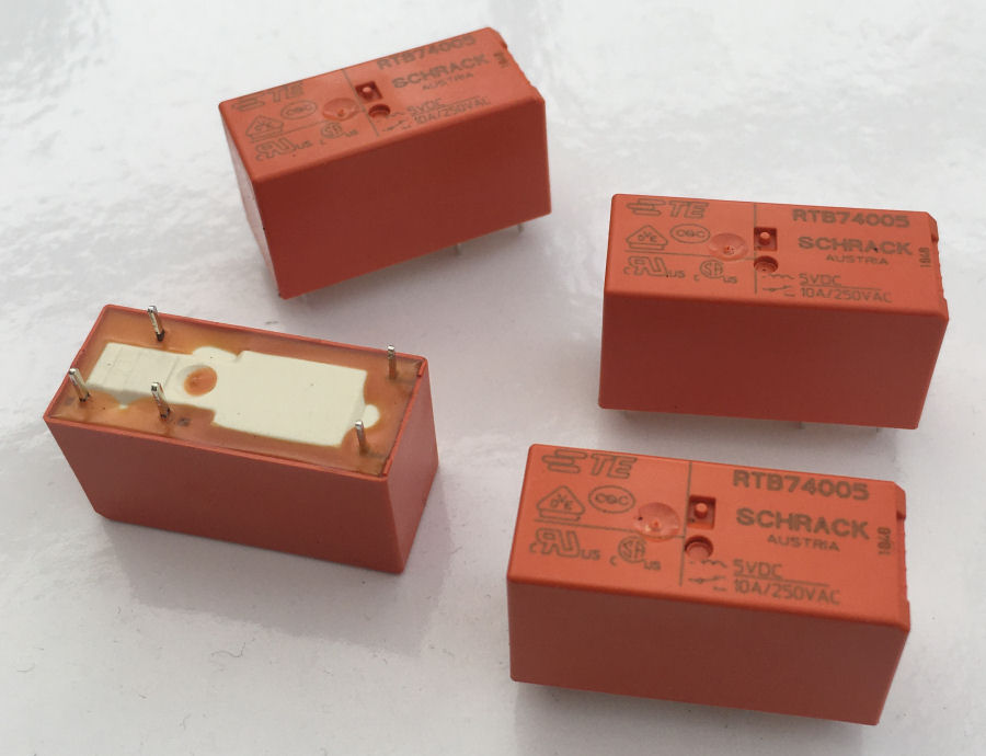
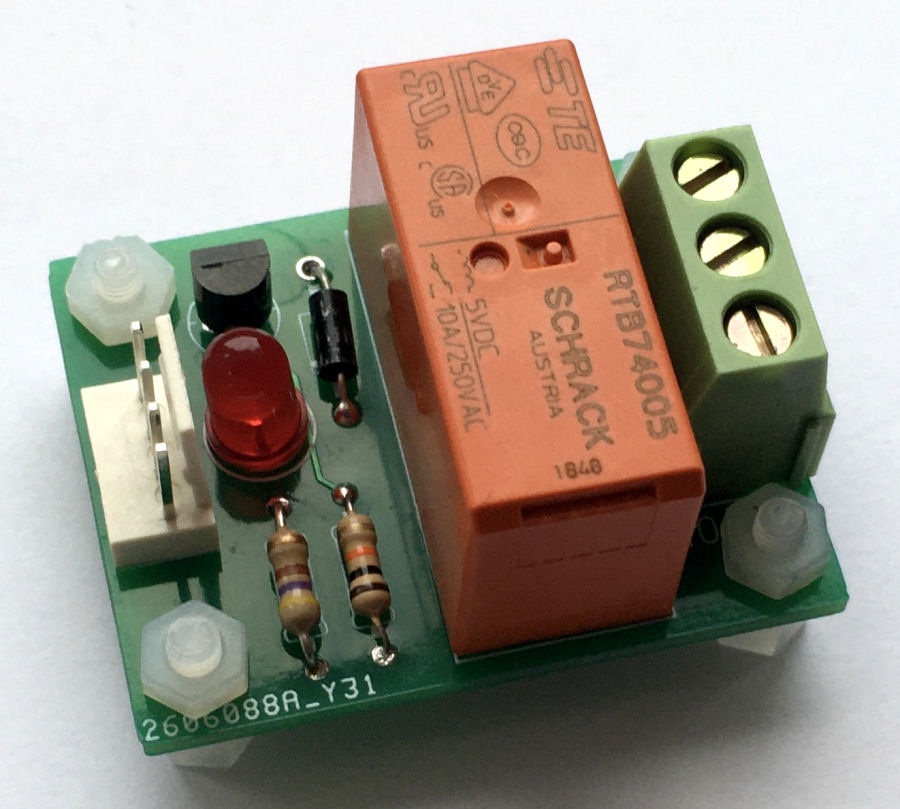
This control board is based around the Schrack RTB74005 relay, which is a 5V dc relay with a 100Ω coil. The single pair of change-over contacts are rated at 10A/250Vac.
These relays are very high quality and reasonably priced at less than £4 each. You can get cheaper equivalents but I'd rather have very good reliability.
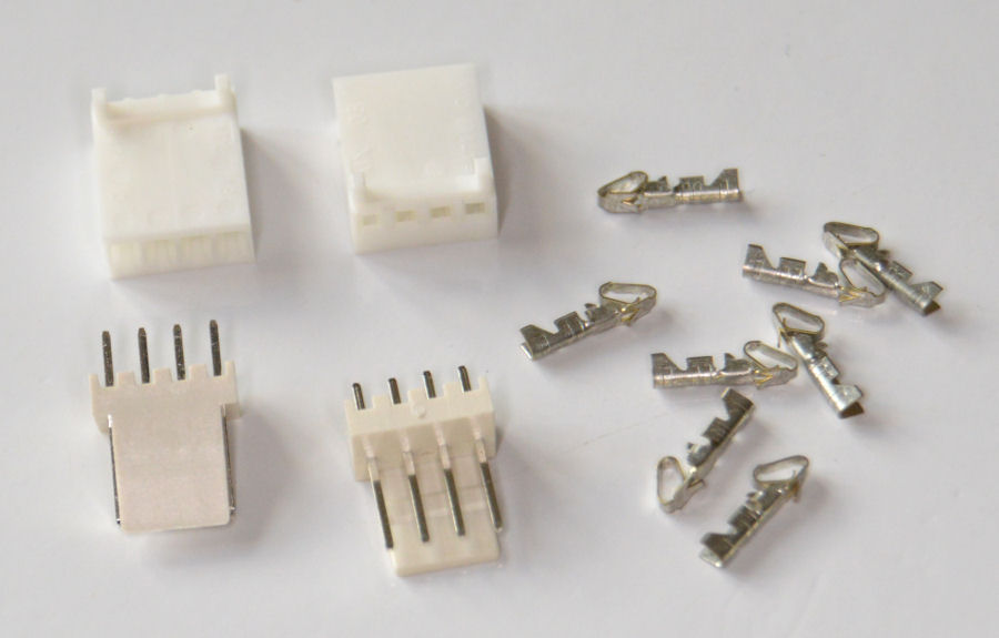
I want to use my 'standard' 4-way Molex connector to connect this board to the many other smart home boards I have produced. The use of these connectors means it becomes another one of my smart home building blocks.
It uses just 3 of the pins on this connector: +5V, GND and the IO pin. The +5V pin is used to power the relay and the IO pin provides the control signal to enable it.
Arduino IO pins do not provide enough power to drive these relays directly. A coil resistance of 100Ω at 5V, requires 50mA which is above the safe limit for most Arduino processors. I'm using a BC547 transistor to safely switch the higher currents involved. The diode is to protect the transistor from back emf from the relay.
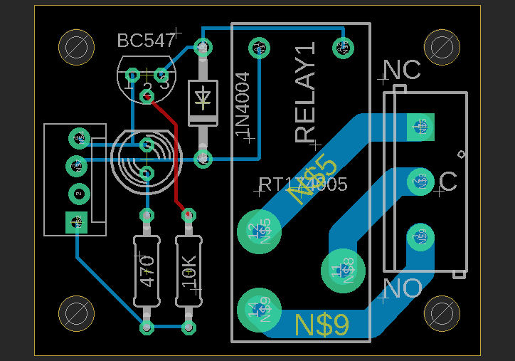
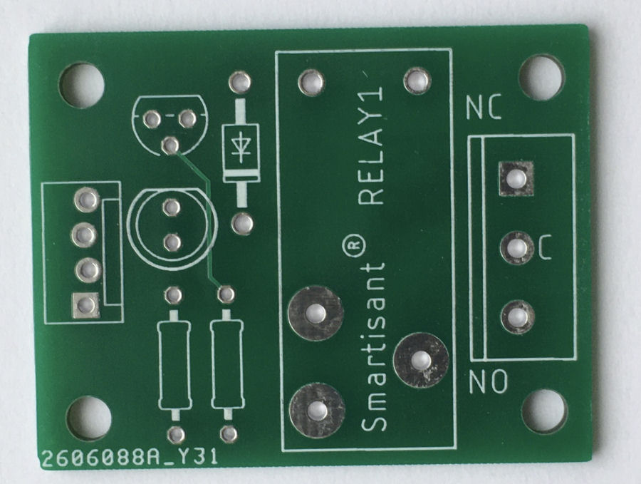
The PCB was designed using Autodesk Eagle and is 40mm × 32mm and features four 3mm mounting holes. The design allows for an optional LED, to provide a visual indication of state.
Although the copper tracks on the mains side of the PCB are quite thick, if I know I am switching currents above 5A, I will add additional wires between the relay contacts and the terminals.
5V Power
It's worth saying a few words about 5V power and Arduinos. Most Arduinos feature an on-board 5V regulator but it has limited power output. It also gets warm quickly if the supplied input voltage is high, e.g. 12V dc. When I use the on-board regulator, I tend to limit the supply voltage to 8.5V dc maximum.
It is possible though to provide 5V dc directly to most Arduino boards and to bypass the on-board regulator, by using a local dc-dc convertor. This can then also supply 5V dc to many other local devices, such as this relay board. This allows much higher loads at 5V and is my preferred way to power Arduinos. It also means that a single dc-dc convertor is required to support PoE.
Build
The PCB was manufactured for me and it is very easy to solder on all the components.
The plan is to integrate this board into an in-line 'smart plug' style enclosure. It is also possible to install them inside a surface box with a standard mains socket on the front.
Testing
- Test the current draw with 5V power supplied. The current drawn is negligible.
- Test relay operation and current draw when 5V is applied to the IO pin. The current drawn is about 50mA and the relay changeover is clearly audible. This includes the LED indicator.
- Test board with mains powered (binary) lighting. This works fine and allows smart home control of many grouped lights, combined to form a high load. This also works with types of lighting that are an inductive load too.
- Test board with mains powered appliances. This works well using this board to switch power to a mains socket, into which an appliance is plugged.
- Test board with a wide range of other mains powered loads.
Smart Home Integration
Over my many years doing smart home (I started in 2004), I have developed my own library of code for Arduino processors and this includes functions to integrate it into my distributed Home Control System and connect numerous types of sensors. These 'slave processors' can then do clever stuff like local control, self-monitoring of performance, local signal conditioning and rate limiting, send warnings and errors, or host some functions locally.
This maximises reuse across my many smart home projects, making it very quick and easy to develop and test new smart home capabilities. My smart home also employs the concepts of technology abstraction, meaning my smart home is also technology agnostic. This allows old technologies or broken sensors and devices to be swapped out with new ones, with minimal effort and zero reconfiguration.
Most of the Arduino processors installed in my smart home use an Ethernet IP network interface, to enable them to send and receive events with my Home Control System, using my unified communications protocol. Wired networks ensure very low latency and hence a great user experience, though occasionally I will use Wi-Fi.
Adding sensors and devices to my Home Control System is simply a matter of adding one line of JSON for each one, to the main configuration file. This defines the name, zone, object type and also the details of the slave processor it is hosted or controlled by. All the intelligence is within my Home Control System, which receives and sends encrypted events using my unified communications protocol. It sends events to update my smart home on things like the temperature, humidity, fan state, appliance and lighting state changes, occupancy, etc.
My contextual smart home models these relay boards as things with a object type, such as Appliance, Fan, Light, etc. Each one then inherits all the features and capabilities of that type and can access all of the common capabilities of my smart home. This means simple, dumb things instantly become super smart just by being connected to my smart home.
Summary
This is actually a really simple piece of electronics but also a useful addition to my smart home building blocks. It allows mains voltages at quite high currents to be easily and reliably switched using an Arduino integrated into my contextual smart home.
The exposure of both normally open (NO) and normally closed (NC) contacts means the board can be used with devices that need to be on by default.
Relays often make more sense that Solid-State Relays (SSRs), especially when it comes to cost.
I have a use case for a much higher power board like this and another project in the pipeline is a 240Vac 40A version. This will safely allow high load appliances and electric heaters to be intelligently controlled too.


