Power Over Ethernet (PoE) Power Injection Board
The objective of this project was to develop a way to support Power over Ethernet (PoE) power delivery to some of the distributed slave processor used in my smart home. This then makes it much easier to install them in remote locations and removes the need to both network and power cables to them.
The main reasons for using a non-standard approach to PoE are much lower costs and simplicity. There is some very cheap open-source hardware available that enables very powerful things in the smart home, with very high reliability and very low costs.

Specifically, this approach should work well with the Funduino W5100 Ethernet module, which I use with the Arduino Mega 2560 Pro. With the Funduino module pin 7 of the Ethernet jack carries negative power and pin 8 positive.
Design
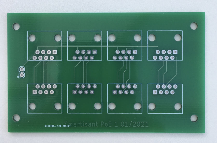
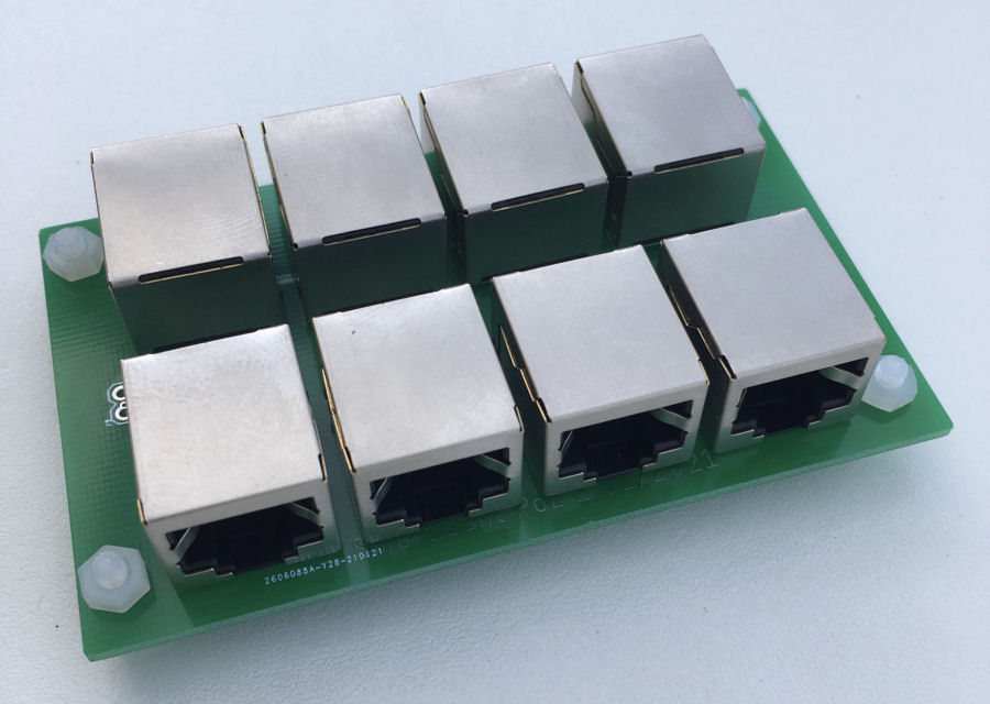
I designed a 4-channel board using Autodesk Eagle. The PCB basically passes through the Ethernet connectivity and allows power to the remote end via pins 7 and 8. Typically, I would use a 12V dc supply, knowing that any voltage drops along the Ethernet cable would be handled by the dc-dc convertor at the remote end.
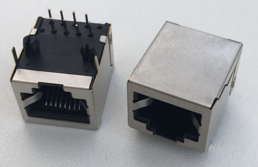
The Ethernet jacks I bought have metal tabs but, my PCB component does not have these. I'm going to see if there is one that does for the next version. The two round holes are for plastic 'push in' lugs. These don't hold the jacks as well as I'd hoped, so I'm also gluing them.
Testing
- The first test was to check that Ethernet works correctly when passed through each of the four channels. This worked fine.
- The next test was to apply 12V dc to the PCB and check it appeared on the right pins on the output sockets.
- It's at this point that I realise my prototype could do with some better labels. These have already been be added to the next version.
- Check power appears on the right pins of the Funduino Ethernet module. It is at this point that things start to go badly wrong :-( The summary explains why.
- Check Arduino Mega 2560 Pro powers up correctly.
- Check PoE power delivery is reliable over 50+ meters of Ethernet cable.
Summary
Once I tried to inject power along an Ethernet cable to the Funduino Ethernet module, things started to go wrong. I was fortunately using a current limiting power supply and no damage was done.
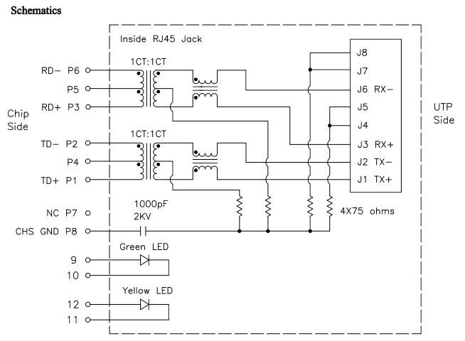
Whilst the pins 7 and 8 are connected to the header on the Funduino board, the HanRun HR911105A Ethernet jack used on this board has some internal electronics and isn't simply an electrical connector like the ones I have used on my own PCB.
The HR911105A datasheet (PDF) shows that this power delivery technique is never going to work.
This is one of those rare things for me, a failed project. I have been misled by the claimed specification of the Funduino Ethernet modules.


