Sonoff Basic Project
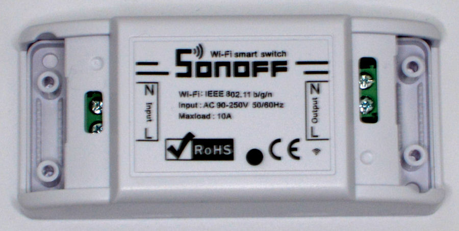
We got hold a couple of Sonoff Basic Wi-Fi smart switches to evaluate and to see how well they work in our DIY smart home. We are not fans of using Wi-Fi for smart home automation but, we are keen to seen how well these devices work given their extremely low cost.
Design
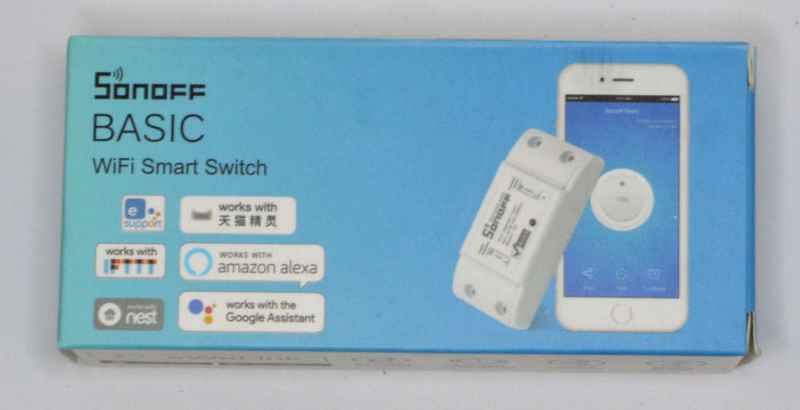
Out of the box it works with the eWeLink app and a number of voice assistants.
Many people 'reflash' these devices with Tasmota, an alternative firmware for ESP8266 based devices, providing sensor support and control via HTTP, serial, MQTT and KNX. This makes it easier to integrate with 3rd party smart home systems.
But we already have our own Home Control System, supporting our own generic, encrypted communications protocol. We have also created an Arduino code library using this.
The reasons and advantages of doing this are:
- We can give the Sonoff Basic a fixed IP address on our home network, to enable reliable and efficient communication over Wi-Fi.
- We can use our own smart home 'unified communications protocol' to control the Sonoff and get updates on state changes reported back to our Home Control System. This basically means it inherits all of the common capabilities of our smart home and instantly becomes really smart.
- It can be intelligently controlled by our smart home and exposed via all of its user interfaces, to enable permissions based control via switches, buttons, voice, text, etc.
The only real question we had over the whole process, was whether the Sonoff Basic has enough memory to allow us to install our code and for it to run reliably. There appears to be no issue though, with our code using 28% of program storage space and the global variables using 33% of dynamic memory.
Build
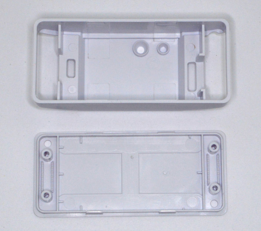
The case is in two parts and they are just clipped together. They are very easy to pull apart. When the cable clips are screwed in place, this cannot happen though.
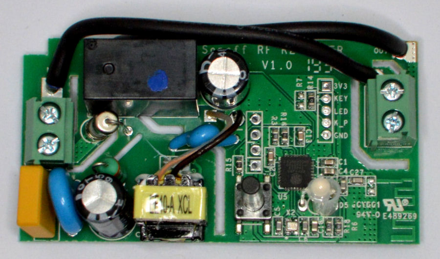
Inside is a PCB with a small on-board dc power supply, a relay (to switch the mains power to the load) and an ESP8266 microprocessor.
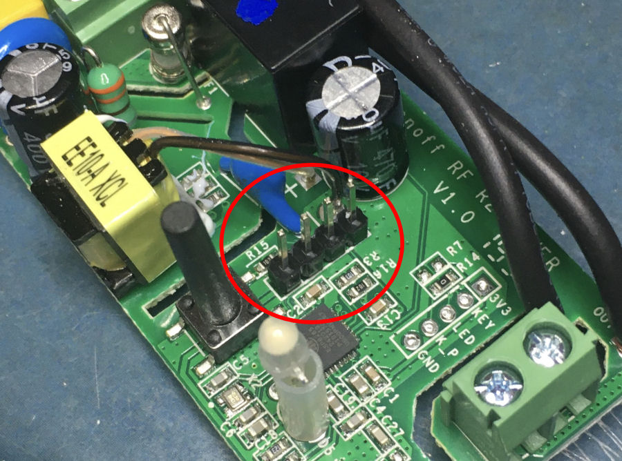
We modified this PCB by adding 4-way header pins to the 4 holes in the middle of the PCB. This allows us to connect a 3.3V FTDI USB-to-Serial converter and use the Arduino IDE (on a laptop) to put own code onto the device.
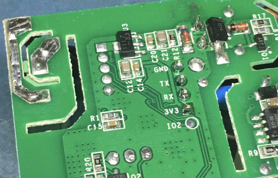
The pins are labelled on the underside of the board. We are using the RX, TX, 3V3 and GND pins.
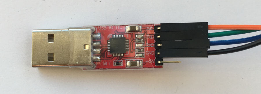
Connections at the 3.3V FTDI USB-to-Serial converter.
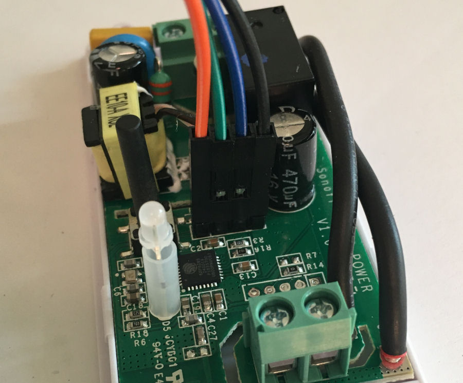
- Orange = 3.3V
- Black = GND
- Green = USB TX -> Sonoff RX
- Blue = USB RX -> Sonoff TX
Arduino IDE
- Install or update to the latest version of Arduino IDE.
- Start the Arduino IDE and go to 'File' > 'Preferences'.
- Under the 'Additional Boards Manager URLs' field, enter: http://arduino.esp8266.com/stable/package_esp8266com_index.json
- Open 'Tools' > 'Board' > 'Boards Manager'
- Search for 'esp8266' and install 'ESP8266 by ESP8266 Community'.
Our Arduino Software
We use Arduino devices a lot in our smart home. Mostly we used Arduino Mega 2560 with an Ethernet shield and our own bespoke Mega 2560 shield. Over the years we have developed a library of code to enable us to prototype and build new smart home capabilities very quickly and easily. This includes and encrypted communications protocol, based around JSON. It allows us to integrate anything and everything really easily. It also enables performance and availability monitoring.
On the Sonoff the LED is pin 13 and the onboard relay is pin 12. We are using the LED to indicate activity and (network) errors.
Reflashing
To boot the ESP8266 in flash mode, you do not plug into the USB port on your computer or connect it to mains power:
- Press and hold the push button on the Sonoff board.
- Insert the FTDI converter USB in your computer whilst holding the push button.
- After 3 seconds, release the push button.
- In the Arduino IDE, start the upload process.
Testing
Testing shows our Sonoff Basic has been 'reflashed' with our own software and is sending 'heartbeats' back to our Home Control System as expected. We can also monitor when it is connected or disconnected from the network and get notifications when this happens. We can also control it via our contextual smart home using any of the available user interfaces.
Testing revealed that the onboard LED pin is actually active LOW on our devices, i.e. you have to set this pin up as an output and set it LOW to turn on the LED.
Debugging
We initially had an issue with debugging via the serial monitor. To use this, you need to leave the FTDI converter in place and remove and then reconnect the 3.3V power line from it to the Sonoff.
Installation
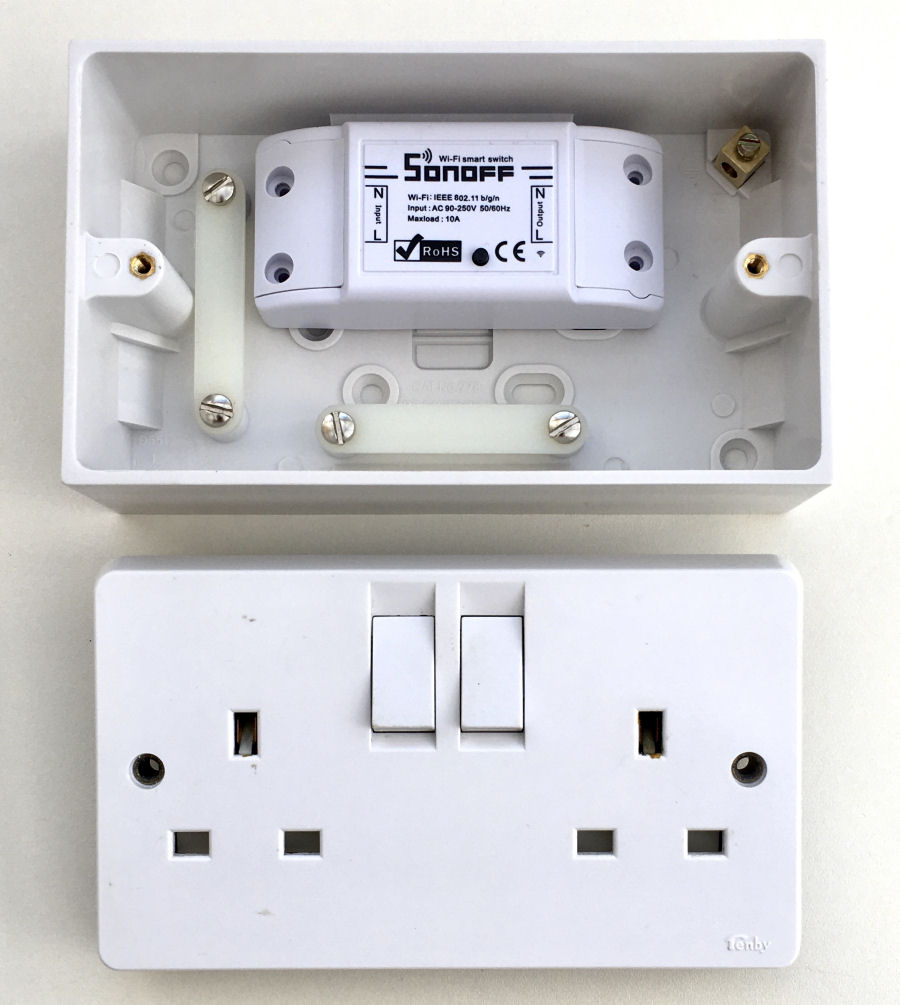
The two Sonoff devices are going to be installed in a 45mm deep 2-gang surface box, with a dual switched socket plate on top. We had the dual switched socket plate spare, so it made sense to take this approach. It also makes the whole thing a lot safer by enclosing all the mains wiring and exposing it via standard mains sockets. This surface box will also not impact on the Wi-Fi range.
The switches add manual isolation capability to the sockets. Using mains socket makes it really easy to plug in anything we want, to enable intelligent control.
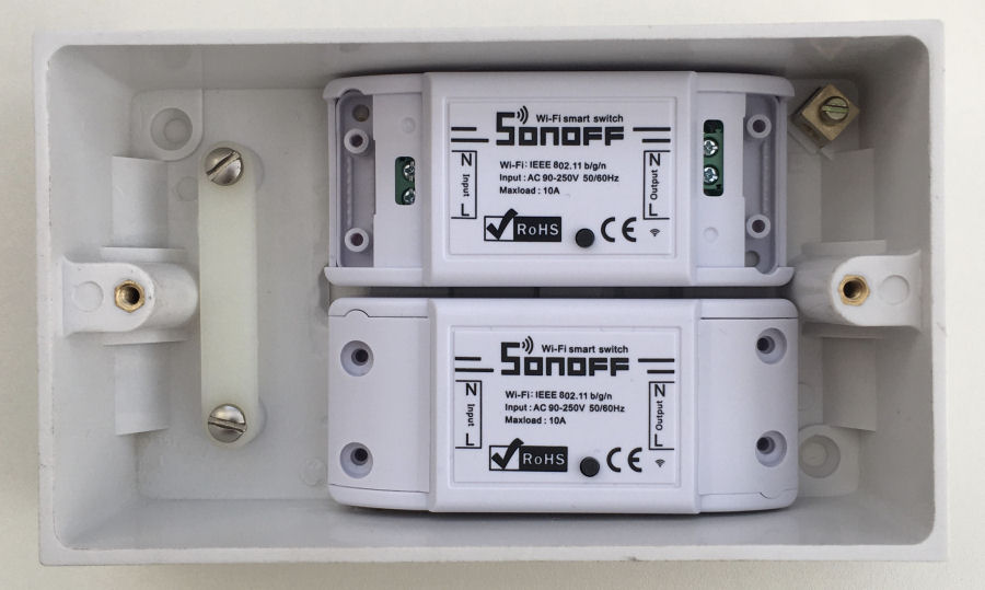
With a bit of work on the inside of the surface box with a multi-tool, the two Sonoff Basic devices easily fit inside the box and there is plenty of clearance and space for the wiring. Power to this box will be via a standard cable and mains plug (with a 5A fuse), so that the whole thing is portable and can be moved if required.
Learning & Insight
Our testing so far shows that the Sonoff Basic device connects to out home network quickly and reliably. We are using a mesh Wi-Fi network around our home, with the same SSID for both 2.4GHz and 5GHz.
This is yet another example of how easily we can connect new hardware to our smart home by using simple configuration and technology abstraction. Abstraction means th at we can assign each Sonoff device a name (e.g. 'Outside Christmas Tree') and a type (e.g. Light) and it then becomes incredibly easy to control the device. It is essentially a 'black box' as far as our smart home is concerned and this the technology could be changed later without requiring any reconfiguration of our smart home.
For a device like this we can assign a software controller, to enable really simple configuration of adaptive schedules (based on occupancy, presence, season, date, time, etc.). This means intelligent powerful control could be achieved by anyone, without technical knowledge or programming. A controller can also use buttons, switches or any other hardware, to enable simple physical control in parallel with the intelligent, automatic control.
Abstraction means that any of our smart home's user interfaces can be used to reference it and we can easily configure permissions, such that guests/visitors are not allowed to control it. Voice control, text chat based control, app, web app, etc interfaces all make our smart home incredibly powerful and simple to use.
We typically model each Sonoff device with a 'type', either a (binary) 'Light' or 'Appliance' and it instantly inherits all of our contextual smart home's common capabilities. This means it can generate a notification if it has been left on, and automatically switched off after a defined time period.
This project isn't about the hardware but the great user experience enabled by it. Having Wi-Fi connected mains powered device means they can easily be moved around our home and can be plugged in where they are required. This is especially useful for items that are not used very often and which are stored away when not in use, e.g. things used in the garden.
Reliability
One thing we are currently looking in to is the reliability of the communications between our Home Control System and the Sonoff Basic devices. This is 100% reliable over a wired Ethernet connection and when using Ardunio Uno or Mega 2560 processors, but we are seeing requests being missed by the Sonoff devices, despite them still being connected to Wi-Fi. This is being investigated further. At the moment, we no don't consider them reliable enough for use in our smart home.


