Smart Home Smart Thermostat

I'm really not a fan of the current range of 'smart thermostats' on the market. They are mostly expensive gadgets designed to be played with, rather than to solve a useful problem subtly, efficiently and effectively.
You can read more about my research and thinking behind this but this project is basically to re-invent the 'smart thermostat' into something much more tightly coupled with my contextual smart home. This project is probably more correctly described as a collection of 'smart HVAC sensors'. When combined with a contextual smart home it makes the smart thermostat redundant.
Objectives
The objectives of this project are to:
- Develop an attractive and stylish "smart thermostat" (smart HVAC sensor) that is cheap, reliable and easy to wall mount.
- To make the 'smart thermostat' as currently sold by the likes of Nest, ecobee, Hive, etc. redundant by replacing all of it's functionality and more .
- To make my "smart thermostat" much smarter and fully context aware by integrating it fully into my contextual smart home.
- To provide much better performance and reliability than all existing smart thermostats on the market, to maximise energy efficiency and minimise heating costs.
- To allow many of my "smart thermostats" to be installed in my home as software instances, saving huge sums of money.
- To create a design that works with all types of heating systems and one that can work with several in each zone and also support many zones.
- My design is as compact as I can make it and the absolute maximum size I'm aiming for is that it will fit comfortably in a standard 35mm deep wall box.
Design
My design is really quite minimalist, with a compact 60mm round display using smoked glass finish, which 'floats' just 6mm off of the wall. Behind this sits a 1.3" SH1106 OLED display that displays the current temperature to 1 decimal place. For 5 seconds in every 60, it displays the relative humidity.
There is no user interface to allow guests, visiting relatives, children, etc. to play with it.
The device is networked via an Ethernet cable or Wi-Fi and provides events back to my Home Control System with timely updates on temperature, humidity and any button presses. This is using my unified communications protocol.
There is no control logic or 'intelligence' in my 'smart thermostat'. All of the control is done intelligently by my contextual smart home, with full whole home context.
Networking
My initial focus is on a wired Ethernet network connection using Power over Ethernet (PoE) but, an Arduino with in-built Wi-Fi would also be an option.
Sensors

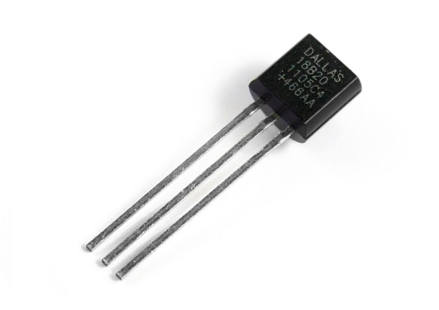
Ordinarily, I would use a Dallas DS1820 temperature sensor as these are fairly cheap and provide good accuracy and reliability. My design will support the DS1820 if required.

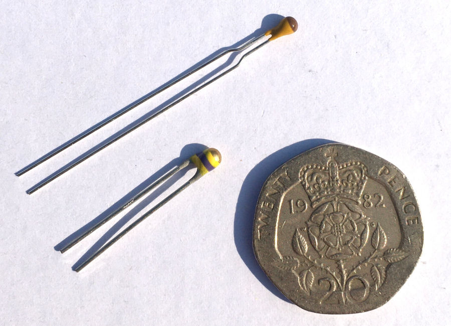
To get the lowest possible latency and fastest possible response to changes in air temperature, my design also supports a bead thermistor.

For the humidity sensor I'm using the Honeywell HIH-4000 series of sensors.

For completeness, it also supports the much cheaper DHT22, which is both a temperature sensor and a humidity sensor.

I hadn't planned to include a light level sensor but a few of my clients were keen to include this in their smart homes.
Display
I've chosen a simple and compact 1.3" SH1106 OLED monochrome display because the primary object of my 'smart thermostat' is accurately sensing and timely reporting. I don't a local heat source in the form of and advanced display and processor, to affect the accuracy of the sensors.
Enclosure

I'm designing the parts of my thermostat enclosure using Autodesk Fusion 360 and will then 3D print them on my Ender 3 Pro 3D printer.
I'm also looking at how the design would fit in a standard 35mm deep wall box. This would make it very easy to install in new builds, requiring just an Ethernet connection with Power over Ethernet (PoE).
User Interface
My 'smart thermostat' doesn't feature and in-built, complex user interface because I have all the user interfaces required to control my heating and hot water already. I don't need any more and I particularly don't want visitors to be able to change the way my heating and hot water works. With my intelligent contextual smart home, the Central Heating and Hot Water is a zero touch user experience that adapts and learns.
If people need to be able to control it, then I will give them permission and access to suitable user interfaces.
One other part of the user interface is a visual indicator on the front (red LED) to provide a warning of any errors (network, sensors, etc.).
Control Algorithm
The 'intelligent' control is no longer a function of my 'smart thermostat' and has been moved into my contextual smart home. The main reason behind this is simply that it makes much more sense, given that my smart home has all of the required context required to do it much more efficiently. This is covered in a lot of detail here.
Implementation & Build

This is my first prototype, to test that all the hardware elements work and also work together. This prototype includes all of the sensors: LDR, HIH-4000, thermistor, DS1820 and DHT22.
Front Cover
The front cover of is simply a 3mm thick, 60mm diameter smoked Perspex circle.
Round Enclosure
The enclosure is basically in three parts. The first part contains the display and the sensors. This is the only bit that you will be able to see once installed. The second part allows this to be fixed to the wall and the third part houses the Arduino processor.

This is the 3D printed enclosure front with the OLED display in place (and a spare one, showing the front). This now has he error warning LED and a compartment for the sensors that allows free air flow around them.

The second part of the enclosure is basically the wall mount and requires a 50mm diameter hole in the wall.
Square Enclosure

The second enclosure design is designed to use a standard wall box, as this makes it easy to install in new homes. With this in mind, I've also designed this square face cover with an inset/flush 60mm diameter Perspex disc. I'm also doing a variant without the OLED display though.

The square faceplate with smoked glass in place.

With the display fitted. The display shows the current temperature for 50 seconds and then the current humidity for 10 seconds, then repeats.
Display
I've chosen a simple and compact 1.3" OLED monochrome display because the primary object of my 'smart thermostat' is accurately sensing and timely reporting. I don't a local heat source in the form of and advanced display and processor, to affect the accuracy of the sensors.

The display is mounted behind a black bezel, which sits behind the smoked from glass. This has two mounting points for an LED and the LDR (light level sensor).
Processor
I'm using a compact Arduino to interface the sensors and this features an IP network interface, to enable it to send events to my Home Control System, using my unified communications protocol. My focus is on the Arduino Mega 2560 Pro to start with as this is very compact and can be easily networked using the Funduino module.
PCB

I had some PCBs manufactured to mount the processor, connect all the sensors and the display. The focus is now on testing this PCB.

This is the made up board with connectors installed to simplify the testing. It supports a wide range of sensors and you only need to install the ones you want to install. The OLED display is also optional.

The use of a Funduino Power over Ethernet (PoE) module means it can be powered via the Ethernet cable or using a local supply between 7V and 32V dc.


