8-Channel Digital Input Board IP1 Project
There will come a point where you want to connect dumb, digital sensors to your smart home and I've been doing this for over 15 years now. To make this really easy, I've developed my own 8-channel optically-isolated digital input boards.
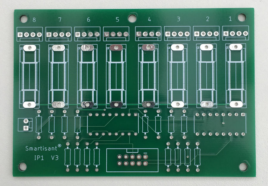
This board is designed to work with Arduino processors, a Raspberry Pi computer and many other devices. The board shown here has fuses for each sensor connected to it.
Design
This 8-channel optically isolated input board part of my smart home building blocks approach to constructing a smart home.
Power Protection
Sometimes you want use individually fused power feeds to sensors, to avoid one sensor failing and potentially taking out the power to the other 7 sensors. For this reason, I designed one version of my input board with in-line fuses for each sensor power connection. This means that if someone accidently cut through a wire (to a PIR sensor for example) and shorted the power to ground, the other sensors will all still keep working.
I have also designed a version without fuses though, to keep the board size small and costs lower. This uses surface mount components. This will be available to buy very soon.
Connectors
In my smart home, I use a standard set of connectors and pin designations.
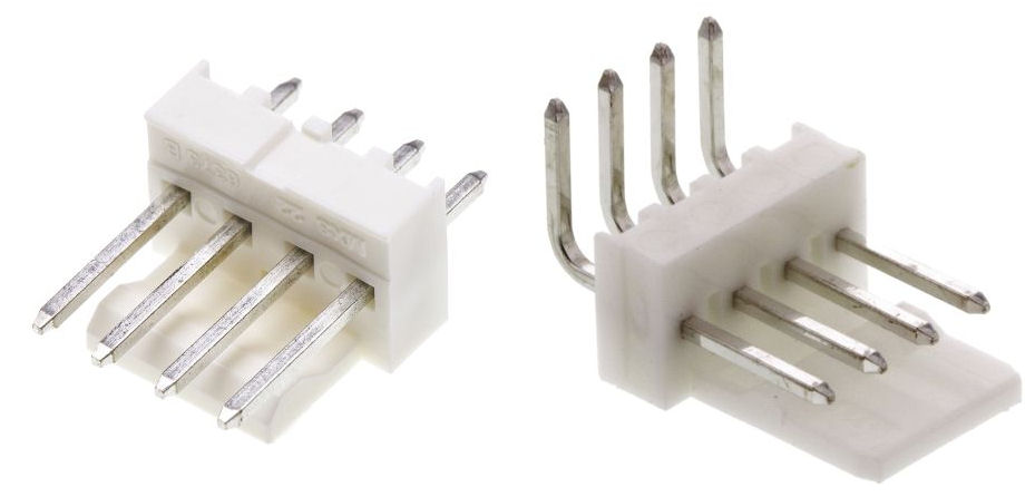
I have standardised on the Molex KK 4-way connector for connecting digital sensors. These connectors are cheap, reliable and compact. The male connector is PCB mounted on the input board.
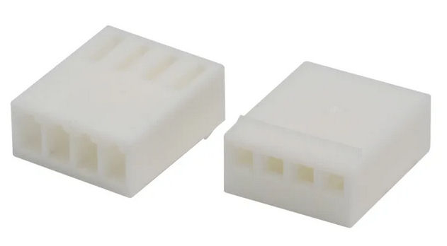
Each sensor is connected via the matching Molex KK 4-way female housing.

The female housing uses these crimp pins. It is worth investing in a good crimping tool as they are quite small. I also solder them as well.
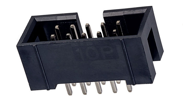
To connect the input board to something like an Arduino, the input board uses a 10-way shielded header connector. A short ribbon cable can then be used to connect it up.
Optical Input Stage
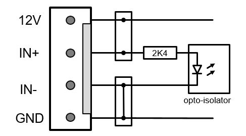
I'm using an optically isolated input stage (using an optocoupler) to provide electrical isolation and enable 12V signalling. This is also much more immune to noise and removes issues with voltage drops over longer cable runs. There are many sensors that are readily available and use 12V dc.
I'm using a 2K4Ω resistor between the 12V signal and the opto-isolator input, to limit the current to about 5mA. In normal operation an installed jumper will connect the IN- pin to GND. A 12V signal on the IN+ pin will then power the input stage of the opto-isolator and the input will then be HIGH.
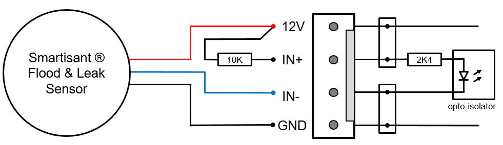
Sometimes you need to connect a device that pulls the input to ground, using an open collector transistor output stage and the Smartisant flood and leak sensor is one such device. This is why there are 2 jumpers, one installed by default (connecting the IN- to GND) and the other not. With this kind of sensor, you would remove both jumpers and connect the +12V to IN+ using a 10KΩ (pull-up) resistor. The sensor would then pull the IN- pin to ground when activated, which would power the input stage of the opto-isolator and the input will then be HIGH.
Optical Output Stage
The output stage of the optocoupler is basically a photo-transistor that can be directly connected to the pins on an Arduino or Raspberry Pi. The board can be used with both 3.3V or 5V processors as the voltage switched to the input pins comes from the processor itself.
To keep the logic simple, my input boards switch +V to the processor input pins and use 10KΩ pull-down resistors on the processor side. This means that in normal operation the processor input pins are LOW. The main reason for this approach was to enable use of a 1KΩ resistor between the processor pin and the opto-isolator, to protect the pin if is mis-configured (e.g. as an output).
It would be possible to do this the other way around and have the photo-transistor pull the input pin to ground. The 1KΩ resistor may then become an issue though as it would act as part of a voltage divider when using an internal pull-up resistor.
Design
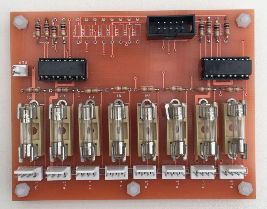
My first version was hand made using Vero strip board. For V2.0, I had a PCB manufactured.

V3.0 is now a Smartisant product in the Smartisant Store.
In Use
As another part of our smart home building blocks approach to the smart home, I have developed my own Arduino shield, to enable me to prototype and build new smart home services and features quickly and reliably. This uses the same 10-way header as this project but, the Molex 4-way connectors on this board are exposing analogue inputs and have different pin connections.
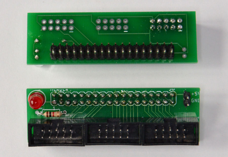
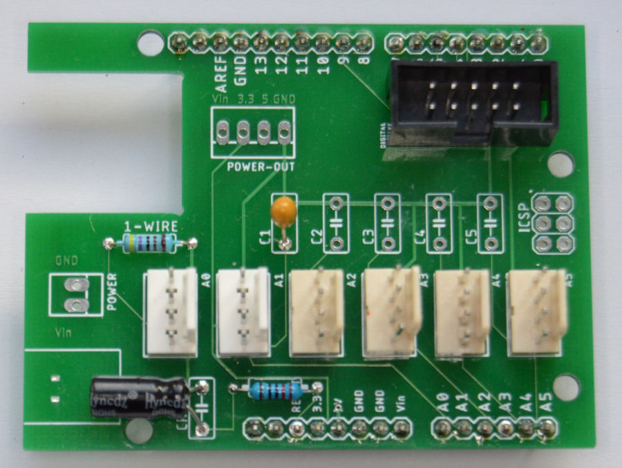
I have also designed this simple header board which plugs into the bottom header on the Arduino Mega 2560 and exposes three 10-way connectors.
This means I can connect 3 input boards and then easily connect 24 digital sensors to my smart home. This is exactly how I have connected every door in my home and 95% of the PIR sensors in it too.
Arduino Software
The software used to send sensor state changes to your Home Control System is going to depend very much on which one you are using. With my own HCS, this is very easy to achieve as it simple expects a message from any slave in the form of an encrypted JSON event.
With an Arduino it is very easy to monitor inputs and even use interrupts if required. The code can cleanse the data and enforce rate limiting. A simple example of this is a wired PIR sensor, which may trigger every 0.5 seconds. You don't necessarily want to send this many events to your HCS, so the Arduino code would enforce that updates are sent at least (for example) 5 seconds apart.
UPS

All of the hardware described here sits behind a protect power supply. I have built my own 12V dc Uninterruptable Power Supply (UPS), to ensure that all the important elements of my contextual smart home keep working during power outages.
Summary
I've been using boards like this for many years in my smart home and they are used to connect a wide range of sensors. It is an incredibly cheap and reliable way to connect sensors to a smart home. The main reason for doing this is to get simplicity and reliability. Wired sensors are just so much more reliable than their wireless equivalents. It is also the only way to get an advanced smart home to scale to many hundreds of sensors, not just from a technology perspective but also from a user experience perspective.
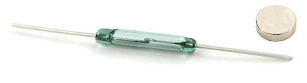
This approach also has one other massive advantage and that is the cost. Connecting 8 doors in our home using wired reed switches to one of these boards cost less than a single wireless sensor using Z-Wave or ZigBee. They can also be installed invisibly and will also be tamper proof. There is also no battery to change regularly. In a new build, this approach is a no brainer!
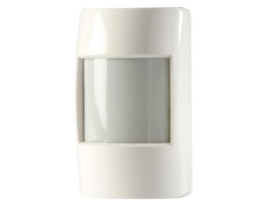
The same can be said with wired 12V PIR sensors. Nearly all the PIR motion sensors in our contextual smart home are connected this way. It also provide much better performance and much lower latency, which is key to a great user experience.
And you can also do this with smoke sensors/alarms and CO sensors.


